This article uses the example of creating a customized project browser and an I-beam size detail schedule to further explain the use of shared parameters, highlighting their similarities and differences compared to other parameter types.
1) Scenario One: Customized Project Browser
Customizing the project browser by setting up project or shared parameters is a common practice to manage numerous views, sheets, and other elements within the project browser. In this scenario, either project parameters or shared parameters can be applied. The deciding factor depends on whether the parameters need to be reused across different projects. For this example, project parameters are used.
The goal of setting parameters here is to organize the project browser efficiently to enhance work productivity and simplify file management. Thus, deciding which project parameters to set and how many to include should be based on analyzing the intended browser organization. The browser’s structure can vary depending on project needs and can be adjusted flexibly.
For illustration, assume a two-level division: “Regulations” and “Sub Regulations.” The following sections will detail how to set and use these project parameters.
To configure project parameters, open the settings under the management panel in the project file. Use the project parameter command to add parameters named “Regulations” and “Sub Regulations.” Make sure to check the categories “Views” and “Sheets” in the parameter editor. This ensures these parameters will appear in the property palette of the corresponding objects.
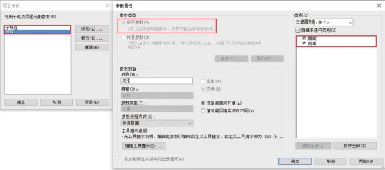
Figure 3-8: Customized Project Browser – Defining Project Parameters
After these settings, open any view, and you will find the “Regulations” and “Sub Regulations” options available in the properties palette. The same applies to any selected sheet. Select each view and sheet, then assign their “Regulations” and “Sub Regulations” attributes in the property palette (see Figure 3-9).
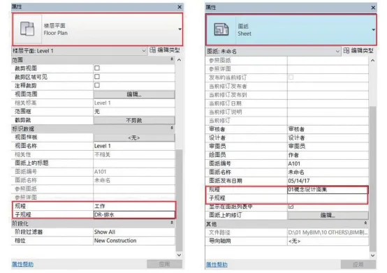
Figure 3-9: Customized Project Browser – Editing Attributes
However, when you check the project browser, it will still be in its default state. This means Revit has not yet used these newly added parameters to organize the browser content. Although the parameters exist, Revit doesn’t recognize that you want to use them for classification.
To fix this, go to the View tab, open the user interface control panel, and select Browser Organization. Create a new category called “Browser Secondary Grouping,” which will automatically open the editor panel. In the “Grouping and Sorting” section, set the grouping to sort first by “Regulations,” then by “Sub Regulations.” After this, revisit the project browser, and you will see views and sheets reorganized according to the assigned attributes.
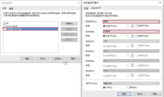
Figure 3-10: Customized Project Browser – Browser Organization Attributes
2) Scenario Two: Creating a Detailed Schedule for I-Shaped Steel Beam Dimensions
The family file contains numerous family parameters. However, as shown in Table 3.2, family parameters exist only within the family editor or project file type editor. These parameters drive changes in family attributes but cannot be used directly for schedules or annotations. In other words, family parameters cannot be output in tabulated data.
Only the default built-in Revit parameters can be used directly for schedules and model tagging. This design reflects that software developers cannot anticipate every parameter needed across all projects, so only universal parameters are built-in. However, practical projects often require specific outputs, analysis, and identification, which is why Revit is highly regarded.
The solution is to define a new set of parameters tailored to project requirements using project parameters. These parameters serve as a bridge to read family parameter values and display them in schedules and tags.
For example, when adding shared parameters to an I-beam family, Revit will prompt for the shared parameter file path on the first creation. Then, you can add and group parameters accordingly. Shared parameters can be complex and project-wide or simple and customer-specific.
As shown in Figure 3-11, create a new “BIM Drawing Shared Parameters” file and add structural parameters, including width and height.
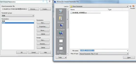
Figure 3-11: Creating a Shared Parameter Text File
Next, open the Steel Beam Family Type Editor, select “Add Shared Parameters,” and browse to the “BIM Drawing Shared Parameters” file to select and add the width and height parameters to the family. If other project parameters are needed later, Revit will access this file path automatically (see Figure 3-12).
Then, use formulas to link the added shared parameters to the family parameters: width (shared parameter) = b (family parameter), height (shared parameter) = d (family parameter). Note that b and d are family parameters created within the steel beam family and do not exist in the project file, so they cannot be shown directly in schedules or tags.
Shared parameters act as a bridge, allowing the project file to access family parameter information.
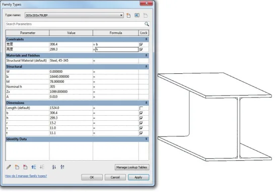
Figure 3-12: Adding Shared Parameters in Family Files
After this, import the family containing the shared parameters into the project file to generate a detailed steel beam schedule (see Figure 3-13).
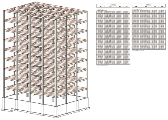
Figure 3-13: Using Shared Parameters to Create a Detailed Schedule in Project Files
From this example, it’s clear that establishing shared parameter files is crucial for effective data management in Revit. Although Revit provides basic built-in parameters, they are insufficient for comprehensive project needs.
Shared parameters can be viewed as a database for building information models. A well-structured database facilitates accurate data input and output. The types of information included should be roughly outlined early in the project. For instance, if the model’s ultimate goal is equipment operation and maintenance, the shared dataset should include relevant equipment parameters. If the model focuses on material inspection or lighting tests, parameters related to materials and lighting should be prioritized.
Despite their advantages, shared parameters introduce challenges such as inconsistent naming and difficulties in data transfer. Solutions may include unifying internal company standards, industry-wide collaboration led by software vendors and organizations, or government-driven standardization through new software platforms that allow adaptive industry evolution. These remain important areas for further exploration.
Source: “BIM Design Software and Drawing – Drawing Practice Based on Revit” by Li Yiyi
For educational and communication purposes only. Copyright belongs to the original author and publisher. If there is any infringement, please contact us for removal.


Must log in before commenting!
Sign Up