In engineering projects, the quality of the formwork system plays a crucial role in ensuring the safety of the entire construction process. As a result, the preparation and execution of formwork system construction plans are subject to strict requirements. This is especially true for tall formwork systems and external scaffolding projects, which must undergo expert verification.
Traditional methods of designing mold frame systems often encounter challenges such as complicated safety calculations, time-consuming drafting, inaccurate cost estimations, and difficulties in on-site communication. BIM technology effectively addresses these issues.
With its visual design capabilities, BIM allows for rapid creation of construction drawings, reasonable analysis of structural stress, and precise calculation of material quantities. Compared to conventional complex floor plans, BIM models provide significant advantages by being intuitive, vivid, and clear during technical presentations.
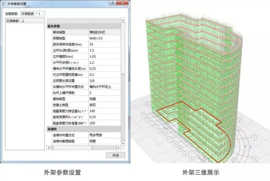
Figure 1: Local nodes of scaffolding
BIM software not only facilitates the construction of three-dimensional building models but also enables the design and modeling of construction auxiliary facilities based on these models. By setting relevant standard parameters, it can automatically generate various outputs such as construction drawings, formwork diagrams, calculation sheets, and material statistics tables. Additionally, it supports three-dimensional sectional displays of the entire building at any level.
Figure 1 illustrates the node diagram of scaffolding derived from the BIM model, where node positions and associated data are clearly defined.


Must log in before commenting!
Sign Up