7. BIM Application for the 160-Meter Continuous Beam Steel Pipe Arch
The 160-meter continuous beam steel pipe arch is illustrated in Figure 5. This project faces several construction challenges, including complex technology, an innovative structural design, a large span, a vertical rotation construction method, and an extended construction timeline. Numerous unpredictable factors arise throughout the construction process, making it a critical and challenging engineering task.
The main implementation steps involve BIM modeling for detailed design, production of component and part drawings, material procurement, cutting and processing, component fabrication, pre-assembly, and on-site construction simulation.
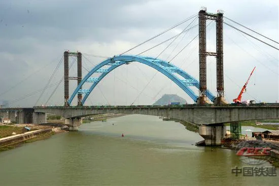
Figure 5: Construction diagram of the 160-meter continuous beam steel pipe arch
8. BIM-Assisted Construction of the South-to-North Water Diversion Project Mainline Crossing
This project features a large-span continuous beam arch with spans of 74m + 160m + 74m crossing over the main canal of China’s South-to-North Water Diversion Project, located within a protected water source area. Strict environmental requirements prohibit any construction fuels, waste, welding sparks, discarded electrodes, paint overspray on arch ribs, or other debris from contaminating the canal, as shown in Figure 6.
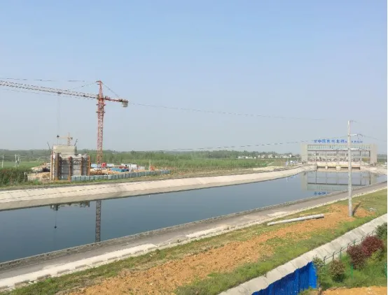
Figure 6: Construction site environment
Solution:
BIM Application Point 1: 3D Construction Site Layout
BIM-based 3D site design was conducted on both sides of the main canal for the continuous beam arch crossing the South-to-North Water Diversion Project. The construction layout carefully considered water source pollution control and traffic restrictions across the canal. The mixing station, steel reinforcement yard, and living quarters were positioned on the right side of mainline mileage DK245+500, away from the protected water source area. Temporary steel reinforcement storage and living areas were located 200 meters outside the protective fences on both sides of the canal, as depicted in Figure 7.
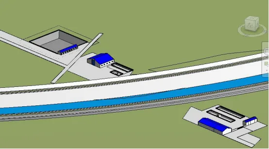
Figure 7: 3D model of the construction site layout
BIM Application Point 2: 3D Visualization of Protective Measures and Hanging Basket Installation
A 3D visualization was employed to illustrate protective measures for the beam hanging basket construction, along with the precise location and structure of the hanging basket installation. This ensured that construction personnel fully understood the plan and that the beam construction process caused no pollution to the water source, as shown in Figure 8.
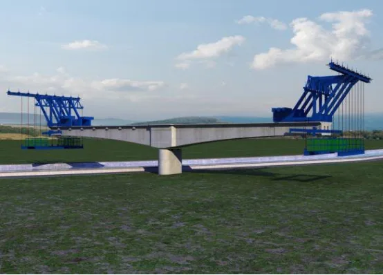
Figure 8: 3D hanging basket installation location and structural diagram
A comprehensive 3D simulation of the entire construction process for the South-to-North Water Diversion Bridge was conducted to accurately display every detail during construction. This simulation supported project execution and ensured zero pollution throughout the process, as illustrated in Figure 9.
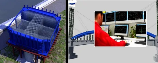
Figure 9: Construction process control
Multiple BIM Collaborative Applications
Using a mobile client, managers can upload 3D models and 2D drawings to the cloud via computer. These models can then be accessed via mobile devices for convenient, on-the-go guidance during construction. This integration of mobile devices, 5D platforms, and cloud services facilitates seamless communication among on-site teams, project groups, and enterprise management, shifting on-site challenges from fragmented to integrated, information-driven solutions.
Progress Management BIM Application
(1) Progress Management Process
By employing project management techniques such as construction progress simulation, on-site photo documentation, and collaborative cloud control, the project maintains timely and efficient progress, as shown in Figure 10.
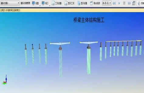
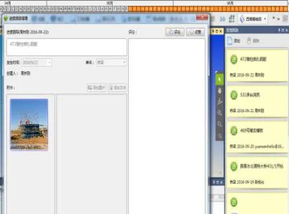
Figure 10: Progress management charts
(2) Comparative Simulation Analysis of Planned vs. Actual Progress
The BIM model segments each component according to construction phases and links them to the schedule to simulate progress. This helps identify potential issues early, enabling plan adjustments. A comparison between planned and actual progress facilitates progress warnings, as shown in Figure 11.
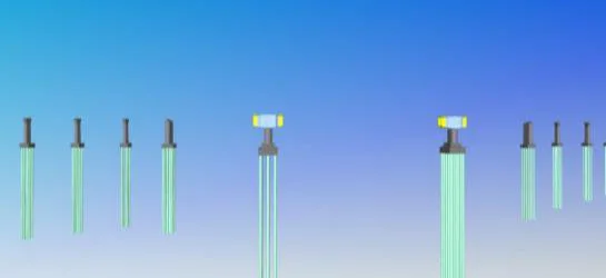
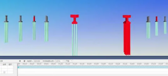
Figure 11: Progress comparison charts
(3) Progress Information Collection
On-site managers document progress daily using mobile devices such as smartphones or iPads by capturing dynamic photos, as shown in Figure 12. This firsthand information is then uploaded to Guanglian Cloud Space via the Guanglian Da BIM5D mobile app.
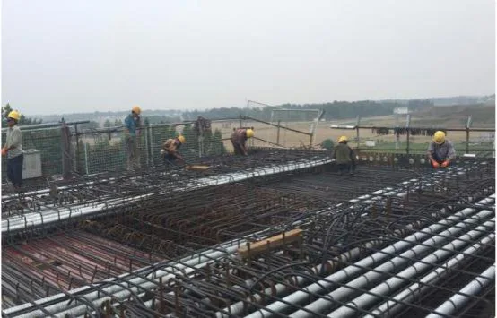
Figure 12: On-site progress documentation
(4) Progress Information Synchronization
Progress photos taken on-site via mobile devices are synchronized to PC terminals through cloud storage. Project departments can monitor real-time progress remotely via PCs, as shown in Figure 13.
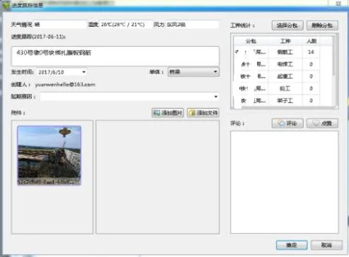
Figure 13: Synchronization of on-site progress data
(5) Overall Web-Based Progress Control
At the enterprise level, the BIM5D management dashboard (the web interface) allows real-time monitoring and comprehensive control of on-site progress, as illustrated in Figure 14.
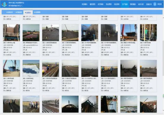
Figure 14: Web-based progress monitoring dashboard
(6) Web-Based Data Sharing
Project technical staff can extract data as needed through the BIM5D management dashboard on the web, enabling synchronized data sharing, as shown in Figure 15.
Figure 15: Web-based data sharing
BIM Application in Material Management
(1) Multidimensional Material Statistics
The BIM platform enables material statistics to be generated in various formats to meet the material demands of different project stages, as shown in Figure 16.
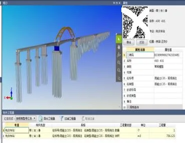
Figure 16: Multidimensional material statistics
(2) Material Statistics Control
By importing the model, total quantities of materials such as steel bars and concrete are calculated. This allows management and construction teams to maintain comprehensive control over material quantities, as illustrated in Figure 17.
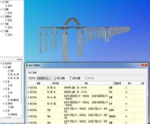
Figure 17: Material statistics control
(3) Project-Level Material Statistics Application
Quantities are selected by material type and workflow segment based on the planned construction schedule. These are submitted to the materials department and extracted via the BIM platform to generate material usage tables according to the schedule. Frontline material personnel use these for quantity verification, helping to control material receipt and distribution.
(4) Single Unit Engineering Quantity Query
The engineering quantity of each component can be queried to provide a basis for material management during construction, as demonstrated in Figure 18.
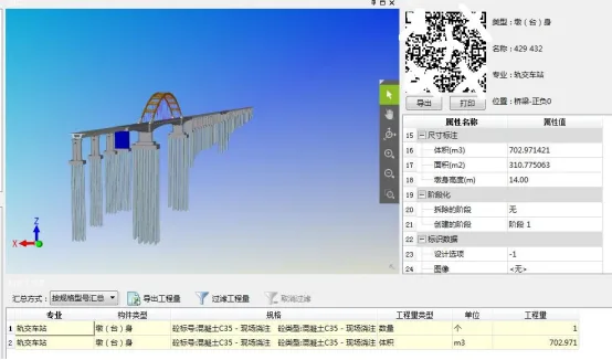
Figure 18: Quantity query interface
(5) Resource Curve Control for Materials
Resource curves are generated based on the construction schedule, specifying daily resource requirements. This allows the project to prepare materials in advance, preventing construction delays due to material shortages. Simultaneously, it tracks each stage of component production, processing, and installation.
(6) Cost Analysis
By associating cost budget documents with BIM models and inputting actual data, cost control is effectively achieved.
Quality Management BIM Application
(1) Construction Quality Control Using the “Push Pin Method”
On-site quality inspections are recorded in real-time using handheld devices linked to the BIM model. Weekly quality meetings review issues, and corrective actions are documented. Inspection results are accessible via the 5D platform on computers.
(2) Quality Inspection and Data Collection
On-site managers collect quality and safety issues using mobile devices, capturing photos and assigning responsibilities. When issues are identified, rectification notices are sent to responsible personnel who then complete corrections, upload evidence, and notify management for acceptance, as shown in Figure 19.
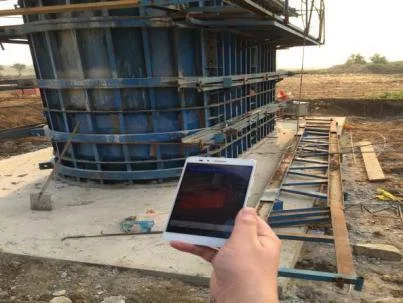
Figure 19: Quality inspection and data collection process
(3) Quality Data Collaboration
At the project level, quality and safety issues are tracked and monitored through BIM5D’s PC and web interfaces, providing real-time insights into on-site conditions and rectification progress. This helps manage overall quality and safety, preventing risks, as depicted in Figure 20. Regular meetings analyze issues, assign responsibilities, and set deadlines for corrections.
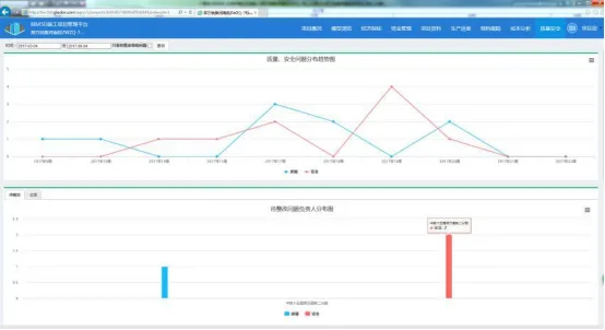
Figure 20: Quality data collaboration dashboard
Innovative BIM Applications
BIM + QR Code Integration
A QR code database has been established where QR codes serve as carriers of material information in bridge engineering, as shown in Figure 21. This system integrates material movement data during bridge construction—including personnel and material images—collected and uploaded via scanning devices to the information management platform and reflected on the BIM 3D model for querying and overall construction progress monitoring.
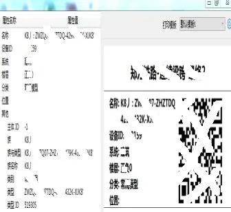
Figure 21: QR code information database setup
BIM + MIDAS Integration
(1) BIM Platform and MIDAS Finite Element Stress and Alignment Integration
The BIM model and MIDAS software operate in tandem to guide each other, performing simulation calculations and structural safety analyses based on Internet and big data technologies for stress and alignment.
(2) Force Analysis
BIM models are imported into MIDAS for stress and linearity analysis, generating cloud-based data visualizations. Comparing measured data to theoretical simulations allows for identifying deviations and implementing timely solutions.
Article by Yang Junjun (Lanzhou Jiaotong University)
For learning and communication purposes only. If any infringement exists, please contact us for removal.


Must log in before commenting!
Sign Up