The newly constructed Zhaohe Town South to North Water Diversion Extra Large Bridge on the Zhengzhou Tuwanzhou Railway is situated in Zhaohe Town, Fangcheng County. It features a distinctive 1-(74+160+74) m continuous beam arch structure spanning the main canal of the South to North Water Diversion Middle Line. This bridge is a controlled project, with the continuous beam arch representing a typical beam-arch combination structure, as illustrated in Figure 1. The continuous beam is built using the suspended basket cantilever method, while the arch ribs are positioned through the vertical rotation construction technique.
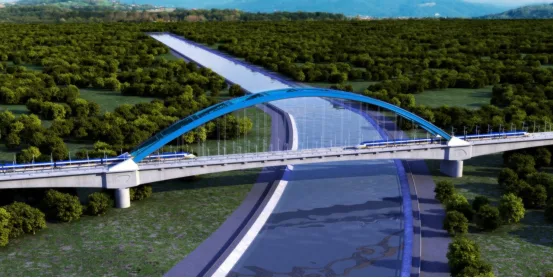
Figure 1: The Zhaohe Town Bridge over the South to North Water Diversion Project on the Zhengwan Railway
Project Challenges
The (74+160+74) m continuous beam arch is rarely applied in high-speed railway dedicated passenger lines. This main span bridge crossing the South to North Water Diversion Project’s main canal in Zhaohe Town is a high-speed railway (operating at speeds over 350 km/h) double-track steel tube concrete tied arch bridge, notable for its innovative design and elegant appearance. The structure’s large span and complexity, combined with advanced technology requirements, demand cross-year construction with an extended schedule.
All construction activities occur at significant heights, involving numerous risks and uncontrollable factors. Additionally, the main canal’s stringent water quality protection standards pose significant challenges. Conventional management methods struggle to effectively address issues related to process control, scheduling, quality and safety management, and environmental protection.
BIM Application and Implementation Plan
1. Objective Analysis and Planning
A comprehensive BIM technology implementation plan was developed for this project. Early on, Revit modeling was utilized to create a 3D layout of the Zhaohe #2 mixing station and Zhaohe steel processing plant, including pile foundations, abutments, pier bodies, continuous beam segments, and standard 32.6m high-speed railway double-line prefabricated box girder families. A family library was established through parameterized settings during modeling, enabling rapid model linking.
Steel pipe arch ribs were designed using the professional steel structure software Tekla and integrated into the overall model. After completing the modeling and integration, a thorough review was conducted to identify and resolve emerging issues. The finalized model was imported into the BIM5D platform, where it was linked with schedule and time information. Cost accounting was synchronized, completing the full process from initial modeling to BIM5D formation.
Considering the linear nature of the project and site management needs, construction technicians used BIM5D mobile devices to collect daily progress data and count on-site workers. Dedicated project managers oversaw quality and safety. Daily updates on actual progress were tracked and promptly communicated to project leaders. Utilizing specialized web modules, management achieved effective on-site control.
2. Project Management Implementation
BIM-based project management focused on three core areas: construction quality control, progress control, and operating cost management. These controls ensured quality assurance throughout the project, timely completion, and cost containment within acceptable limits.
3. Development of Implementation Standards
Project completion and acceptance required adherence to engineering standards set by the acceptance party. To meet these requirements, a suite of standards was developed, including BIM implementation guidelines, system technical standards, overall plans, work specifications, model component standards, specialized application standards, and delivery standards.
Before modeling, the enterprise BIM technology center formulated detailed BIM modeling standards covering model naming conventions, materials, storage protocols, collaboration workflows, and model delivery reviews. Personnel promptly updated models as needed and provided regular BIM software training tailored to technical staff expertise levels.
Regarding BIM5D platform usage, the BIM engineer updated the project schedule daily, reviewed data collected by site technicians, and uploaded updated files to the web data module. They compared planned versus actual progress, monitored forecasted versus actual completion, and promptly reported findings to project leaders for informed decision-making. Access permissions on the web platform were allocated to project and company leaders to ensure comprehensive oversight. BIM applications were systematically integrated into project management processes with regular evaluations.
BIM in Technical Management
1. Visualized Drawing Review
During modeling, technical personnel collaborated to visually inspect drawings for conflicts and issues before construction, as shown in Figure 2. This early detection of design errors prevented delays caused by drawing discrepancies. For example, in the K13 section steel bars, the A4a layout diagram showed 90 bars, whereas the steel bar quantity table listed only 45. The 3D steel bar arrangement model confirmed the correct count of 90 bars, revealing a discrepancy in the design drawings. Similar issues were quickly identified through 3D steel bar arrangement inspections.
Additionally, for the 0 # block of the 60+100+60m continuous beam, the modeled quantity was 475.04 m³. The design drawings indicated 125.31 * 2 + 51.875 * 2 = 354.37 m³, showing a concrete quantity shortage of 120.67 m³, providing a basis for revision.
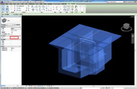
Figure 2: Visual Drawing Review
2. Reinforcement Design Optimization
Collisions between steel bars and corrugated pipes were simulated and analyzed, allowing for three-dimensional technical guidance on the spatial arrangement and binding of steel bars. This proactive approach resolved on-site drawing conflicts before construction began. Further simulations identified collisions between ordinary steel bars and vertical prestressed ducts and tensioning slots. Based on these collision analyses, steel bar models were prepared in advance and delivered to the site for predictive planning, as shown in Figure 3. The simulation detected 130 collisions between steel bars and corrugated pipes.
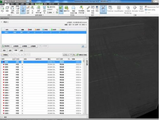
Figure 3: BIM Family Library Creation
3. Reinforcement Detailing and Construction Drawing Guidance
For complex tray-shaped steel bars, such as N7, which progressively change along a hyperbolic curve, conventional manual calculations are insufficient. Using Revit modeling, CAD drawings were exported to guide steel bar prefabrication and processing on-site, reducing steel waste.
For nodes with densely packed steel bars, BIM-based pre-arrangement provided visual instructions to workers, minimizing errors in steel bar sequencing and positioning during construction. Specifically, for the large and dense reinforcement volume of the 74+160+74m continuous beam arch 0 # block, BIM pre-arrangement disclosed detailed steel bar information to workers, reducing errors. For example, BIM allowed extraction of individual A3C steel bar details, specifying cutting sizes and guiding on-site installation.
4. 3D BIM Disclosure of Metal Corrugated Pipe Ducts
Design drawings for continuous beams only provide coordinates for select cross-sectional metal corrugated pipe ducts, making it difficult to intuitively determine their positions relative to each beam section boundary. Leveraging BIM’s powerful sectional functions, relative coordinates of cross-sectional ducts were flexibly extracted as needed. This enhanced technical disclosure and established a foundation for intelligent prestressing construction.
5. 3D BIM Disclosure of Component Quantities
High-speed railway linear engineering involves many irregular components with complex quantity calculations prone to errors. Accurate Revit modeling combined with the Guanglian Da BIM5D platform’s quantity extraction function enabled flexible, precise quantity retrieval. BIM engineers provided technical disclosure forms to site technicians for effective communication and coordination.
6. On-Site Reporting of Concrete Components
Site technicians deducted steel bar and metal corrugated pipe quantities based on received volumes and completed concrete pouring orders to apply for concrete pouring, as illustrated in Figure 4.
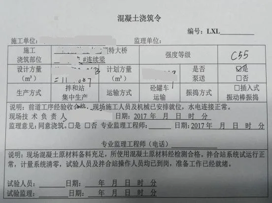
Figure 4: On-Site Quantity Report of Concrete Components
To be continued
Article by Yang Junjun (Lanzhou Jiaotong University)
For educational and communication purposes only. If any infringement occurs, please contact us for removal.


Must log in before commenting!
Sign Up