For the first time, BIM technology and the Internet of Things have been integrated into the construction management of the Xuhonghe Extra Large Bridge on the Xuyan Railway. The project spans a main line length of 31.526 km with a total construction period of 41 months. Key construction tasks include relocating and upgrading three electrical systems, building the lower sections of the beams, fabricating and installing box girders, cast-in-place beams, and bridge deck systems. The Xuhonghe Extra Large Bridge features a (100+200+100) m continuous beam arch (see Figure 1) and is situated in a high seismic fault zone, presenting complex design and numerous components.
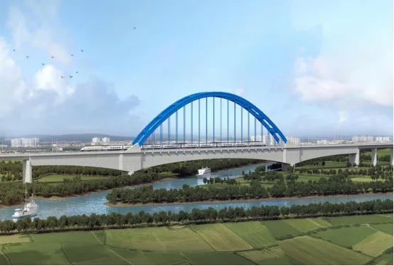
Figure 1: Xuyan High-Speed Railway Bridge
Application of BIM Technology
Using Revit software, modeling of the entire 31.5-kilometer railway line has been conducted. Since there are currently no prior case studies, especially regarding BIM application for long-span high-speed railway bridges, this project serves as a pioneering effort. Based on the project’s unique characteristics, key BIM application areas have been identified, including full-line progress management, application to the (100+200+100) m continuous beam arch, and tracking management of prefabricated box girders.
Basic BIM Applications
1. Establishing a Standard Family Library
Unlike traditional building projects, BIM applications for high-speed railway bridges require a specialized family library. Since Revit’s default library lacks railway-specific components such as bridges, roadbeds, and tunnels, this project developed a parametric family library tailored for Revit bridges (see Figure 2). This will facilitate broader BIM usage in future high-speed railway bridge projects.
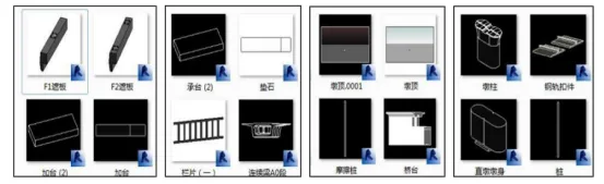
Figure 2: Establishing a Group Standard Family Library
2. Automated Quantity Calculation Using BIM
BIM enables automatic quantity calculations, significantly reducing manual workload during construction. For example, this project involves 9,670 pile foundations. Using Revit and custom family libraries for pile foundations and bearing platform steel bars, steel bar parameters are automatically extracted, laying the groundwork for precise engineering quantity statistics (see Figure 3).
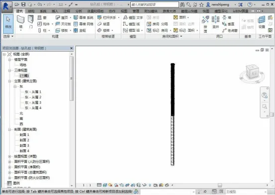
Figure 3: Automated Calculation of Engineering Quantities
3. Parameterized Modeling of Civil Engineering Components Using Revit
Utilizing Revit modeling, the technical team created parametric models for various structural sections such as pile foundations, pier caps, pier bodies, and beams following established standards and guidelines. Additionally, steel bars were parameterized based on 2D drawings. Tekla software was used to model steel structures, including steel truss members and the 100+200+100 m continuous beam arch, allowing detailed arch models to be developed. Creating separate models for each component sets a foundation for integrated modeling later (see Figure 4).
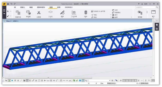
Figure 4: Parameterized Modeling of Civil Engineering Components
4. Design Drawing Review
During modeling, discrepancies between component and structural drawings are identified and resolved through coordination among stakeholders to avoid design issues that could delay construction. For example, a 48m steel truss beam model revealed inconsistent bolt hole placements on the crossbeam web plate of the lower chord ME4 between member and bridge deck panel diagrams. The design team was informed promptly, and adjustments were made in advance (see Figure 5).
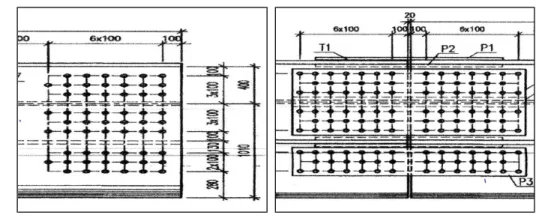
Figure 5: Design Drawing Review
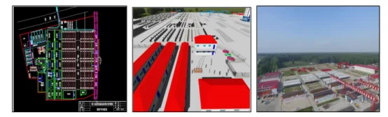
5. Optimization of Beam Field Layout
Beam field layouts are initially designed using CAD drawings. Subsequently, a 3D model is created based on these drawings to guide on-site layout accurately (see Figure 6).
Full-Line Progress Management
1. Traditional Progress Management Challenges
Traditional text-based schedules lack intuitiveness and real-time tracking capabilities. They only provide abstract progress indications, making it difficult to identify flaws or analyze actual construction progress effectively.
2. BIM-Based Progress Management and Tracking
The BIM platform visually represents on-site construction deployment (see Figure 7). Different colors indicate construction status: green for completed sections and red for areas with no progress. This approach facilitates planning the next phases efficiently. Integrating data on the BIM5D platform allows monthly construction simulations and optimization of scaffolding teams’ schedules. Concrete completion quantities extracted from the model are compared with actual site data to monitor progress and identify delays.
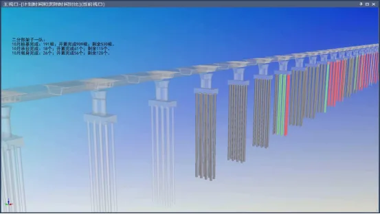
Figure 7: Progress Management and Tracking
3. Progress Monitoring Using Drones
By comparing UAV aerial photography with BIM progress simulations, delayed sections were identified for on-site inspection and accelerated work scheduling (see Figure 8).
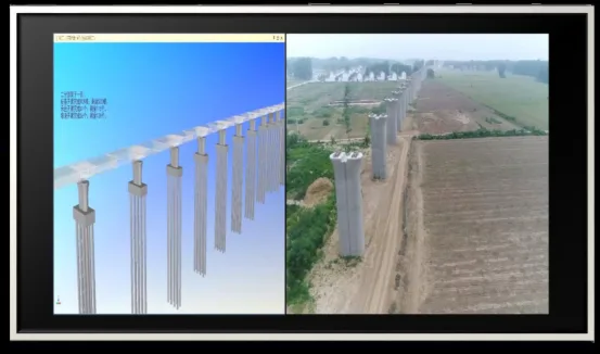
Figure 8: Drone-Based Progress Management
4. Progress Tracking with QR Codes
QR code-based progress management was implemented for the entire section’s special structures, enabling real-time control of construction progress (see Figure 9).
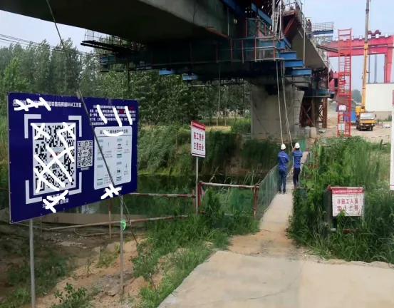
Figure 9: Progress Management via QR Codes
BIM in Three Key Areas
The (100+200+100) m continuous beam arch spanning the Xusha River presents challenges due to poor geological conditions, high technical complexity, and construction difficulty, making it a critical component of the Xuyan Railway project (see Figure 10).
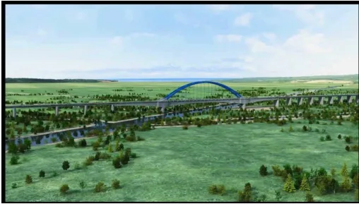
Figure 10: Xusha River Continuous Beam Arch Bridge
1. Geological Modeling with AutoCAD Civil 3D
The route crosses two distinct geological zones: the Xuzhou Fault Fold Bundle and the Subei Depression, separated by the Tancheng Lujiang Fault Zone. The fault zone, located between DK96 and DK115, is a highly active seismic area with a history of magnitude 8.5 earthquakes (see Figure 11). A geological model was developed using AutoCAD Civil 3D to understand these complex features.
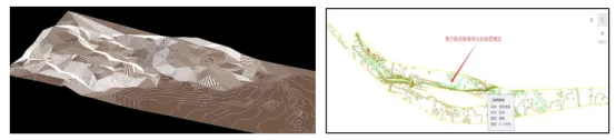
Figure 11: Geological Model Created with AutoCAD Civil 3D
2. Scheme Comparison and Selection
Located in a high seismic fault zone with a peak ground acceleration of 0.3g, the project required careful structural selection. Multiple steel purlin structure models were developed in Revit and compared. Ultimately, a steel sheet pile structure meeting all performance requirements was selected (see Figure 12).
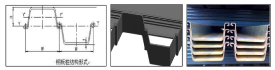
Figure 12: Steel Sheet Pile Structure
3. Foundation Pit Excavation Simulation
The foundation pit’s force system changes continuously. Using BIM, a structural model of the pit was created and excavation plans were simulated to visualize system transformations, simplify design schemes, and support expert reviews. Due to its proximity to waterways and poor geological conditions, the continuous beam arch main pier’s deep foundation pit excavation is highly complex. Midas structural analysis software was used to analyze strain on the cofferdam structure, ensuring construction safety (see Figure 13).
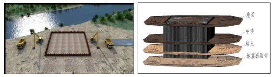
Figure 13: Foundation Pit Model and Structural Diagram
4. Collision Detection Report
Using Navisworks for collision detection, multiple clashes were identified between steel bars and corrugated pipes. The collision report facilitated prompt communication with the design team, preventing delays caused by design conflicts (see Figure 14).
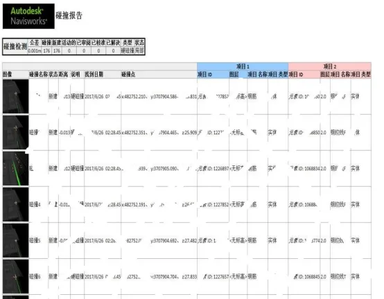
Figure 14: Collision Detection Report
5. BIM and 3D Printing
3D printing technology was used to create solid models of complex arch components, allowing detailed assembly and layout breakdowns (see Figure 15).
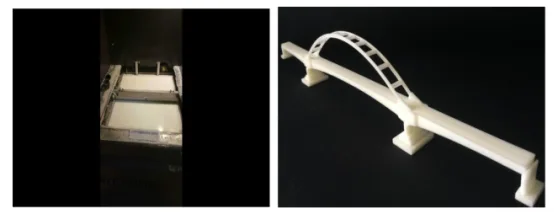
Figure 15: 3D Printed Arch Structure
6. Tracking and Management of Prefabricated Box Girder Process
Traditional Management Challenges: Managing prefabricated box girders traditionally faces several issues: difficulty in controlling construction status and onsite information; challenges in progress control, including process coordination and material management; and high communication costs due to delayed or fragmented information flow.
BIM and IoT Enhanced Management: Leveraging BIM and IoT, process managers can scan QR codes on mobile devices to update the status of box girders in real time. Construction site dispatchers can monitor component statuses remotely via computers or mobile devices, reducing delays caused by processing or transportation inefficiencies and improving overall project progress control (see Figure 16).
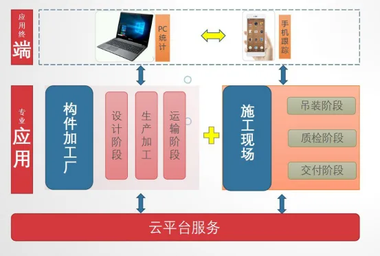
Figure 16: Box Girder Production Management Mode
Prefabricated box girders require planned input. Site dispatchers enter monthly plans into the BIM management platform, set tracking stages aligned with fabrication processes, and assign warning colors to monitor progress effectively (see Figure 17).
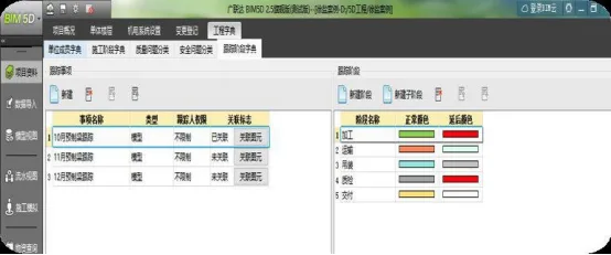
Figure 17: Plan Input for Prefabricated Box Girders
Workers can use mobile phones to scan QR codes on-site, update the actual stage of box girders, and enable real-time engineering quantity calculations (see Figure 18).
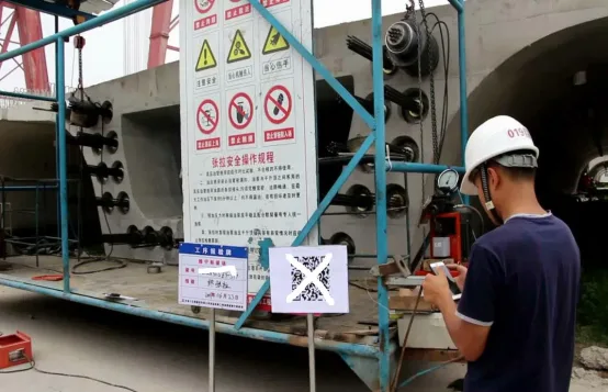
Figure 18: Actual State Input of Prefabricated Box Girder
Based on cloud platform data analysis, dispatchers can query box girder statuses at any time on computers or mobile devices, monitor workflow counts on web interfaces, and take timely action to prevent delays. Color coding indicates progress status: green for completed tasks and red for delays. Monthly and annual statistics are continuously updated (see Figure 19).
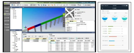
Figure 19: Prefabricated Box Girder Status Query and Warning
Article by Yang Junjun (Lanzhou Jiaotong University)
For educational and communication purposes only. If any infringement occurs, please contact us for removal.


Must log in before commenting!
Sign Up