This article uses the Wuhan Country Garden East Project as a case study. Located in Huashan Ecological New City within the Donghu High-tech Zone of Wuhan, the project sits at the intersection of Huashan Avenue and Huacheng Avenue. It spans a total area of 131,400 square meters, with an overall construction area of approximately 180,000 square meters. Below is the first project rendering.
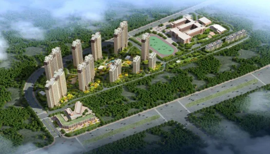
Figure 1: Rendering of the Country Garden Dongjing Project
The project features a monolithic concrete shear wall structure. Building 6 serves as an example for analysis and research. Covering approximately 27,000 square meters, Building 6 consists of 32 floors above ground and one underground level. The architectural rendering of Building 6 is shown in Figure 2 below. The building’s exterior walls, select interior shear walls, staircases, balcony panels, and air conditioning panels are all prefabricated and manufactured off-site.
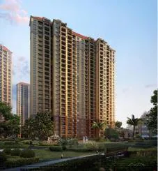
Figure 2: Architectural Rendering of Building 6
The key project details are summarized in Table 1 below.

Table 1: Project Information Summary
Development of BIM Model and Construction Simulation
2.1 BIM Modeling
To create the project information model, BIM modelers first analyze the 2D CAD design drawings supplied by the design institute. They study architectural design specifications, overall layouts, floor plans, sectional views, structural floor construction drawings, as well as production drawings and material lists for prefabricated components on each floor. This comprehensive review enables the creation of an accurate 3D model.
Autodesk Revit is used to build the 3D models, Microsoft Project prepares the construction schedules, and Navisworks facilitates construction simulation and progress visualization. Due to article length constraints, the progress management analysis focuses on a typical floor of Building 6. Figure 3 shows the completed 3D model of Building 6.
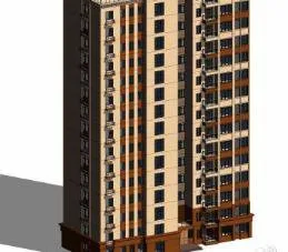
Figure 3: 3D Model of Building 6
The overall project schedule shown in Figure 4 was developed by breaking down the project structure by component type and then preparing it using Microsoft Project.
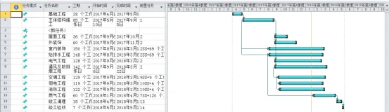
Figure 4: Overall Project Schedule
The preliminary schedule and 3D model were imported into Navisworks to link the schedule with the building component information. Additional data required for construction tasks was integrated into the model, enabling dynamic construction simulation. Figure 5 illustrates the simulated construction progress.
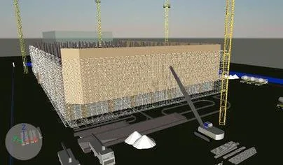
Figure 5: Construction Progress Simulation
2.2 Real-Time Information Updates
Construction management personnel record daily site progress, documenting the completion of various processes and tasks at each time point. They upload data, photos, and text updates to the cloud via mobile devices such as smartphones or iPads. Correspondingly, the actual progress of the main structure is automatically updated on the cloud-based BIM management platform.
3. Progress Management
3.1 Schedule Analysis
Using Navisworks for progress simulation, the schedule can be reviewed to identify issues early and implement corrective measures.
As shown in Figure 6, the green highlights indicate that the structural columns on the first floor are currently being poured and constructed. BIM’s visualization capabilities clearly show sufficient work fronts to maintain normal construction flow. While template support and formwork tasks for the columns are not depicted here, it is critical to complete formwork before casting the structural columns.
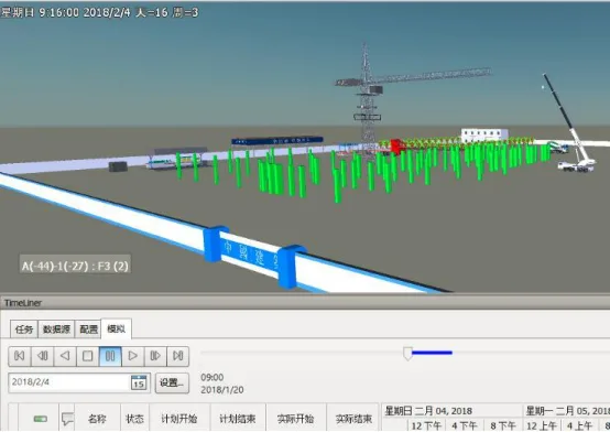
Figure 6: On-site Pouring of First Floor Structural Columns
According to the initial schedule, the structural framework of the seventh floor is complete, providing adequate workspace to begin hoisting prefabricated exterior wall panels on the eighth floor. Thus, exterior wall installation on the eighth floor can commence, as shown in Figure 7. This confirms the effectiveness of BIM technology in validating the preliminary schedule.
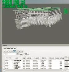
Figure 7: Hoisting of Prefabricated Exterior Wall Panels on the Eighth Floor
The Navisworks simulation reveals that after casting the structural columns on the standard floor, the original schedule plans to start hoisting prefabricated interior walls. However, there is enough workspace available to simultaneously cast some interior walls in place. Therefore, it may be beneficial to adjust the schedule to allow prefabricated interior walls to be hoisted concurrently with the cast-in-place interior walls.
However, the simulation also identified insufficient workspace during prefabricated staircase hoisting, indicating scheduling conflicts in the initial plan. This necessitated rescheduling the staircase lifting. Through multiple simulations, an optimized construction schedule was developed to avoid spatial conflicts and improve subsequent scheduling during construction.
3.2 Component Production
Following initial component segmentation, Revit is used to create models of prefabricated components. Each component is defined as a “family,” preparing for assembly and the establishment of a component model database.
(1) Component Model Library
The component library is categorized into exterior wall components, interior wall components, air conditioning panels, balcony panels, and more. By standardizing the component library, this project replaces traditional methods of modeling walls, slabs, and columns with custom-built family assemblies. Each family is created based on actual prefabricated dimensions and contains detailed material, size, and performance attributes. An example of an exterior wall family is shown in Figure 8.
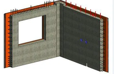
Figure 8: Example of Exterior Wall Family
(2) Production Components
After detailed component design is completed, production begins. Designers upload models to the cloud-based BIM management platform, enabling production personnel to fully understand design intent through the component data available online.
Before completing the current construction floor, the external wall demand plan is submitted to manufacturers based on standard floor requirements. Each floor requires 24 types of prefabricated exterior wall panels. Manufacturers develop production schedules and mold production plans according to the number of exterior wall types in the model. During production, personnel can view the properties of each panel, understand the wall structure, hole positions, and screw overlaps, providing accurate, intuitive information to standardize component manufacturing.
3.3 Component Installation
In this project, staircases are prefabricated in the factory. Prefabricated stairs serve as an example to illustrate how construction simulation guides on-site assembly. To enhance seismic resistance and ease of installation, factory-produced stairs use flat formwork and hinged joints.
Key Points for Prefabricated Staircase Installation:
- Before hoisting, verify that the cast-in-place surface of the stair beam is level. If not, use shims to ensure the staircase will be horizontal after installation.
- During lifting, control points are located at the four corners of the staircase. Lifting rings connect to pre-embedded connectors, and steel wire ropes are used in tandem.
- When the staircase reaches 1.5 meters above the lifting surface, secure the upper and lower ends with steel wire ropes to keep it within the control zone.
- Maintain balance throughout the lifting process as much as possible.
Figure 9 shows a simulation of the prefabricated staircase lifting process using Navisworks, which helps guide on-site workers.
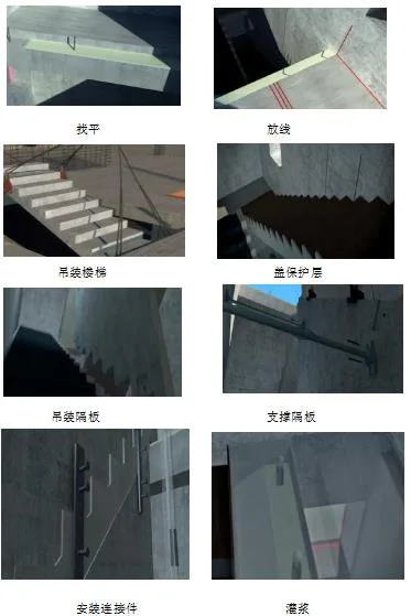
Figure 9: Simulation of Prefabricated Staircase Lifting
During tower crane lifts, many specialized terms related to prefabrication can be unfamiliar to on-site teams. This often leads to time-consuming explanations and complicates the lifting process. Simulating the entire procedure ensures workers clearly understand each step and the key points involved, improving efficiency and safety.
Content source: Li Wenshuang (Wuhan University of Technology)
For educational and communication purposes only. Copyright belongs to the original author. If any infringement occurs, please contact us for removal.


Must log in before commenting!
Sign Up