The entire secondary structure is based on the main structure, and traditional two-dimensional methods cannot accurately represent all spatial relationships. To provide an intuitive presentation for the owner and general contractor, and to facilitate communication and decision-making, we adopted BIM technology to address these challenges.
1. Construction Simulation: The crown steel structure installation in the office building primarily involves two tower cranes: the ZSL2700, positioned at the center of the core tube, and the ZSL750, located at the northeast corner. These cranes operate independently. After completing the installation of the crown’s bottom frame, the ZSL2700 crane is removed. Subsequently, the ZSL750 continues working alone until the tenth floor crown structure installation is finished. Then, an M37OR tower crane is set up on the north side of the L67 floor to remove the ZSL750 crane, while completing component installation in the affected areas.
During the crown steel structure installation, a support tire frame must be placed directly under the crown’s bottom frame node. The L67 floor structure beneath this frame requires temporary reinforcement. Once the bottom frame is welded and forms a stable system, the support tire frame can be removed.
The crown structure should be hoisted and installed starting from the northwest corner, extending outward to both sides, ensuring stability throughout the process. After forming a stable system, timely measurement, calibration, high-strength bolt installation, and welding are performed.
This project utilized Navisworks software to simulate and analyze the crown structure construction process. Based on simulation results, a reasonable construction sequence and method were developed. When necessary, temporary measures such as supports and connecting beams were introduced to ensure smooth completion within the scheduled timeframe. See Figure 13.
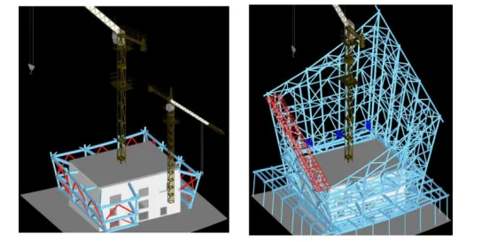
Figure 13: Construction simulation
2. Steel Structure Node Simulation: The complexity of steel structure members, involving multiple steel pipes connected to a single node, required detailed simulation using Tekla software, as shown in Figures 14 and 15.
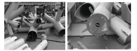
Figure 14: Site Detail of Cast Steel Node
This project employed 20 cast steel nodes located 305 meters above the core cylinder top. Each weighs between 4-6 tons and is made from G20Mn5qt steel. These nodes serve as transition trusses between the upper and lower crown structures. Due to their complex shapes and numerous branch pipes, manufacturing and installation were challenging.
When lifting these nodes, surrounding members were not yet installed, leaving them suspended. To ensure stability during installation, support measures were implemented under the two main longitudinal members, with one support point per member. The supports consisted of standard H300x300x10x15 steel, with adjustable steel plates for elevation control. Radial steel pads were positioned on each branch pipe’s end face, with the pad center serving as the control point.
Throughout construction, precise support, measurement, lifting techniques, and personnel coordination ensured high-precision, high-altitude assembly. The results met installation accuracy requirements.
Traditional connection methods like welded or bolted ball joints struggle to meet modern steel structure demands in terms of construction, manufacturing, and installation. Advances in computer technology and casting have introduced cast steel nodes as an effective alternative, favored for their strength, plasticity, toughness, and versatility. Compared to traditional nodes, cast steel nodes offer several advantages:
- Factory casting: Nodes are cast as a whole and undergo heat treatments such as normalizing and quenching, eliminating stress concentrations and residual stresses common in welded joints.
- Design flexibility: Node shapes can be optimized based on structural requirements, stress distribution, and manufacturing processes.
- Higher load capacity: With thicker walls than welded joints and chamfered intersecting lines, cast steel nodes withstand greater loads.
In this project, the crown structure’s fourth floor was transformed into two rows of internal and external truss structures connected by horizontal, top, and diagonal web trusses, forming a spatial pipe truss system. The horizontal truss acts as a transition between upper and lower structures.
Inner truss nodes, the main load-bearing points, involve up to 11 intersecting members at narrow angles. To meet strength requirements, all nodes within this circular area were designed as cast steel nodes, totaling 20 nodes with a maximum weight of approximately 6 tons.
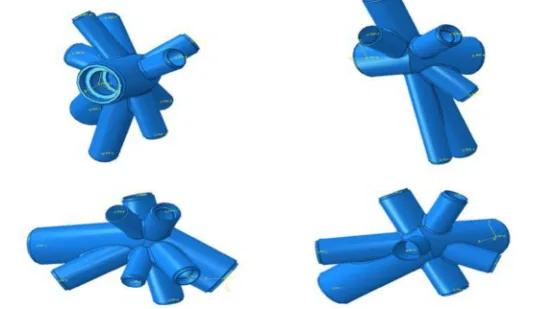
Figure 15: Tekla simulation effect diagram
3. Additional Applications: BIM technology also clearly represents the spatial relationships of each unit, which is crucial for determining the size and orientation of the computer room space. Revit models optimize building piping design by integrating various specialized pipelines, simplifying engineering tasks with comprehensive building equipment and piping solutions (see Figure 16).
Adding lighting effects to BIM models simulates building landscape lighting at night, offering 3D dynamic visualizations that enhance the homeowner’s experience and support decision-making.
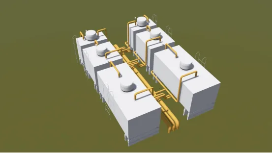
Figure 16: Mechanical and Electrical Professional Model
Challenges and Summary:
The steel structure’s complexity and unique shape made the construction process challenging. Traditional 2D plans were insufficient to meet design and construction demands. Modeling was done without relying on 2D drawings, resulting in intricate spatial relationships and complex point selections. The supporting steel frame top had to align closely with the track’s bottom plane, requiring very high accuracy.
Collision detection after modeling revealed many intersections that required resolution, including during construction simulation and steel node simulation phases, necessitating close collaboration with the construction team.
Overall, the project demanded analysis and solutions addressing the construction process, main techniques, technical guarantees, scheduling, and duration safeguards. The application of BIM technology effectively resolved steel structure construction and installation challenges.
Because the entire secondary structure depends on the main structure and spatial relationships cannot be fully conveyed through traditional 2D methods, BIM provided an intuitive platform for owners and contractors, enhancing communication and decision-making.
Structurally, multiple calculation software tools were used for node analysis, dynamic elastoplastic analysis, and wind tunnel simulation, demonstrating BIM technology’s maturity and versatility. However, some issues remain, such as project cost calculations, which are limited due to financial accounting constraints.
By applying BIM during construction, the process becomes visualized through simulations, showing spatial relationships and component interactions before actual construction. This allows for evaluating construction methods, understanding component orientations, internal forces, and deformations, and comparing multiple approaches. BIM supports proposing installation principles, selecting control parameters, optimizing construction plans, reducing accidents, and ensuring the quality and safety of complex structures. Ultimately, this shortens construction time and enhances economic benefits.
Article by: Guohui
For learning and communication purposes only. Copyright belongs to the original author. If there is any infringement, please contact us for removal.


Must log in before commenting!
Sign Up