The roof crown of Tower 1 spans an elevation from 297.850m (L67M level) up to 345.95m at the tower’s peak. This intricate spatial structure stands 46.745 meters tall and incorporates approximately 1,500 tons of steel. Its distinctive design, reminiscent of a crown, gives the structure its name. Please refer to Figures 1 and 2 for visual references.
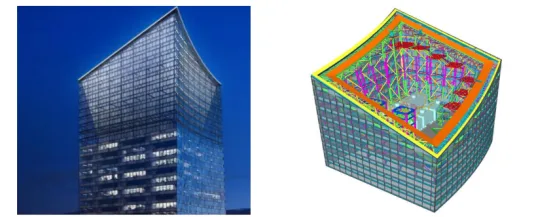
Figures 1: Rendering Figure 2: Tekla Model
Structural Features: The crown structure features an irregular “back” shape that originates from the core tube at the 67th interlayer (L67M) and extends upward with reinforcing hoops, reaching the L69 level. At the fourth layer, located at the core tube’s top, the structure transitions into two rows of frames—inner and outer—connected by horizontal trusses, roof trusses, and diagonal web members, forming a spatial pipe truss system.
The vertical composition of the crown is divided into 10 layers. The northwest corner reaches the highest point at 10 layers (elevation 345.95m), while the southeast corner is the lowest at 4 layers (elevation 311.880m). Both the southwest and northeast corners share a height of 7 layers (elevation 328.555m). The east and west faces of the crown consist of curved surfaces. See Figures 3 and 4 for details.
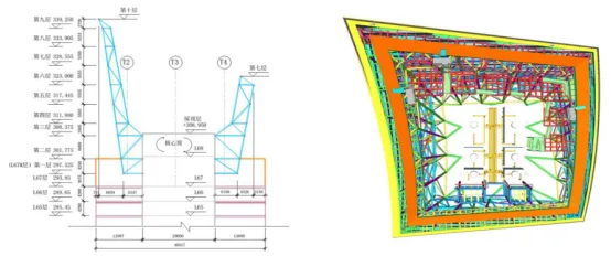
Figure 3: Side Elevation View Figure 4: Top View
Design Challenges: Given the crown’s full steel construction and its complex spatial configuration, traditional 2D drafting methods fall short in accurately conveying its intricate geometry. To provide clear visualization for the owner and the general contractor, and to streamline communication and decision-making, BIM technology was employed.
Leveraging the BIM design platform, various calculation software tools were integrated to perform intelligent analysis on nodes, overall seismic resistance, and wind environment factors. This approach showcases the advanced capabilities and versatility of BIM technology. Refer to Figures 5 and 6.
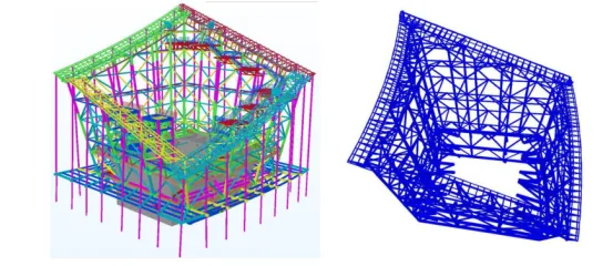
Figure 5: Tekla Modeling Figure 6: Structural Analysis with SAP2000
Construction Challenges: The crown’s secondary structure comprises three main components: the south side window cleaning machine support frame, the roof slope window cleaning machine support frame, and the satellite dish platform support frame. According to the overall construction schedule, installation begins with the south side window cleaning machine support frame, followed by the roof slope support frame, and finally the satellite dish platform support frame.
Construction sequencing and installation challenges were addressed through BIM-based construction simulation. See Figure 7.
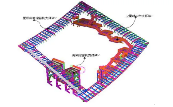
Figure 7: Crown Secondary Structure
(a) South Side Window Cleaning Machine Support Frame: This frame features a straightforward structural design. The installation sequence is as follows: embedment parts (column bases) → steel columns → steel beams and diagonal supports → lifting of the top truss section → installation of secondary beam components → addition of auxiliary structures such as steel grating, stair railings, and ladders. See Figure 8.
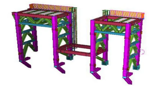
Figure 8: Support Frame for South Side Window Cleaning Machine
(b) Roof Slope Window Cleaning Machine Support Frame: The support frame is divided into four sides—east, west, north, and south. Installation is planned to start from the south side, followed by the east and west sides, and concluding with the north side. Refer to Figure 9.
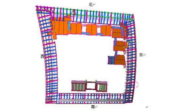
Figure 9: Support Frame for Roof Slope Window Cleaning Machine
(c) Unique Challenges for Roof Slope Support Frame: For functional reasons, this support frame is double-sided and inclined, with the east and west sides shaped as continuous arcs. Moreover, due to the constraints of the completed main crown structure, the layout of these support frames is irregular, making traditional planar coordinate measurement methods unsuitable.
To overcome this, BIM technology was employed for precise measurement and positioning by linking the refined design model’s spatial coordinates with the actual on-site coordinates. This ensures that any component’s 3D coordinates in the model align perfectly with reality.
Coordinate spheres were established within the refined model as needed, each labeled according to a consistent numbering system. The 3D control coordinates for required components were then exported to facilitate measurement and positioning of this complex spatial structure. See Figure 10.
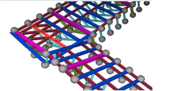
Figure 10: Coordinate Sphere in 3D Model of Roof Slope Window Cleaning Machine Support Frame
(d) Satellite Dish Platform Support Frame: This support frame consists of seven satellite dish platforms, two winch room platforms, three parking platforms, and steel staircases connecting them.
The platforms are constructed from H-shaped steel with fully welded rigid joints. The seven satellite dish platforms are cantilevered structures located on the inner east and north sides of the crown, supported by diagonal braces.
These platforms connect via steel staircases directly to the roof floor. According to structural requirements, installation proceeds from bottom to top: first the roof steel staircase, followed by the satellite dish platforms and their connecting staircases. The adjacent winch room and parking platforms are built concurrently. See Figures 11 and 12.
During installation of each satellite dish support frame, the slant supports are installed first, followed by the platform frames to ensure a stable structural system.
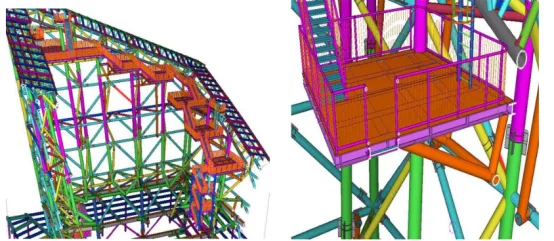
Figure 11: Satellite Platform Figure 12: Single Satellite Platform
Article by: Guohui
For educational and communication purposes only. Copyright belongs to the original author. If infringement occurs, please contact us for removal.


Must log in before commenting!
Sign Up