The Shenyang Fortune Center super high-rise project is located in the Financial and Commercial Zone of Shenhe District, Shenyang City. This Grade A office building offers a total usable area of 20,500 square meters and a construction area of approximately 110,000 square meters. The building features six underground parking levels and 44 above-ground floors dedicated to office space, including two refuge floors. The total height reaches 187.1 meters, with the main roof and floor structure standing at 179.9 meters. See Figures 1 and 2 below.
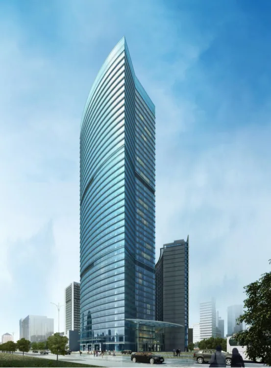
Figure 1: Architectural Rendering
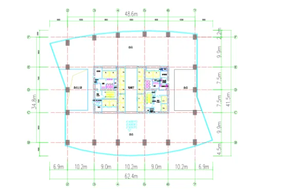
Figure 2: Standard Floor Plan
2. BIM Model Creation: First, the architecture, structure, and equipment disciplines build their respective models using Revit Architecture, Revit Structure, and Revit MEP. These discipline-specific models are then linked together to form a comprehensive model operating on a unified platform. This integrated model accurately reflects the building’s physical attributes and construction logic, ensuring all views—plans, elevations, and sections—are interconnected. Any modification in one view automatically updates corresponding changes in others in real time, as illustrated in Figures 3, 4, and 5.
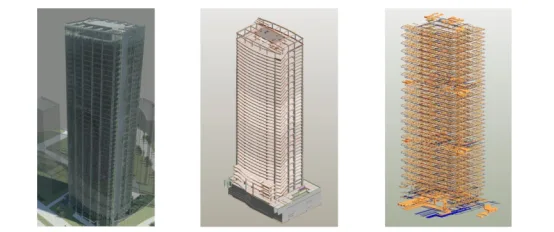
Figure 3: Architectural View Figure 4: Structural View Figure 5: Equipment Comprehensive Pipeline View
3. BIM Collaborative Design: This project leverages the powerful BIM suite to unify information and data across disciplines on a common platform, enabling seamless data sharing and smooth communication. For example, once the structural engineer completes the structural model in Revit Structure and hands it off, equipment engineers can directly open the model in Revit MEP without conversion, linking structural and equipment models effortlessly. Similarly, architects can link equipment and building models to exchange data swiftly. This approach replaces traditional isolated design workflows, which are laborious and time-consuming. Real-time updates prevent critical errors such as electrical conduits penetrating walls or equipment pipelines conflicting with main structural beams, which could compromise structural integrity.
With BIM collaborative design, any update made by a designer instantly propagates across all related models, eliminating conflicts and ensuring accuracy.
Additionally, collision detection plays a crucial role in this project by identifying conflicts between models, such as between structural elements and equipment pipelines. Once the positions of beams and columns are fixed, collision detection verifies if equipment pipelines interfere with the structure. Given the complex and dense pipeline arrangements in the basement and equipment layers (see Figure 6), careful coordination among disciplines is essential. BIM collision detection (shown in Figure 7) precisely identifies clashes and professional conflicts, allowing timely adjustments. This integration ensures that changes made in one discipline are reflected across all others, significantly reducing errors and improving efficiency compared to traditional workflows.
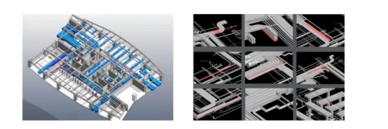
Figure 6: Layout Plan of Refuge Floor 7 Equipment Collision Detection
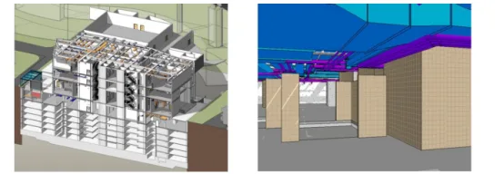
Figure 7: Basement Section Figure 8: Basement Roaming
Moreover, the architectural, structural, and equipment models are not only three-dimensional but also viewable from multiple perspectives. Traditionally, generating detailed elevations, sections, and node details posed challenges. BIM simplifies this by allowing users to quickly generate section lines to observe relationships between plans, elevations, and sections (see Figure 8). Changes in one view automatically update others. Adding a building component instantly displays its 3D view and section details. This clarity helps each discipline understand the structure’s interior, reducing low-level errors common in traditional design and boosting design quality and efficiency by eliminating repetitive tasks.
Finally, the project utilizes BIM’s real-time walkthrough function, which acts like a mobile camera navigating inside the building. This feature is especially valuable in the basement, where the complex structure and dense pipelines increase the risk of inter-disciplinary conflicts. By setting a walkthrough path, designers can inspect the layout and pipeline arrangements from a third-person perspective, making the design more intuitive and vivid (see Figure 9). This walkthrough can also be rendered as an animation, providing a realistic visualization for construction teams and owners.
4. BIM in Architectural Design: In the early project stages, BIM software such as Revit and Lumion is used to simulate the building scheme. This allows owners to experience the finished design beforehand, make informed decisions, and reduce costly later adjustments. See Figures 10 and 11.
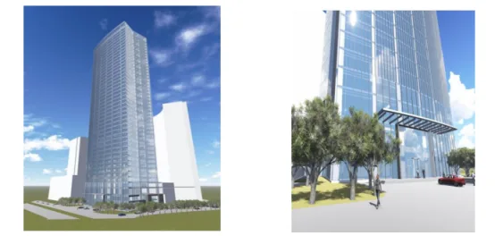
Figure 10: Overall Architectural Rendering Figure 11: Partial Architectural Rendering
Using BIM technology to arrange interior room functions enhances spatial visibility for owners, allowing direct evaluation of design themes and reducing costs associated with design changes. See Figure 12.
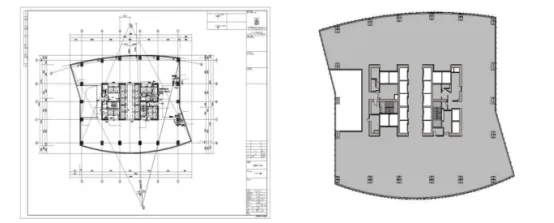
Figure 12: Architectural Space Visibility
The project also employs BIM for quantity takeoff, helping owners estimate budgets early and supporting effective cost control throughout the project lifecycle. Refer to Figure 13.
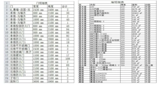
Figure 13: Building Parts List Statistics
5. BIM Integration with Structural Calculation Software: This project uses Revit API to import models from YJK (Yingjianke) structural calculation software directly into Revit. The process involves reading and processing external model files, automatically matching families for structural elements like beams and columns, and merging segmented beams and slabs. The model is then created and edited within Revit, including unit conversions and adding new family types.
The YJK structural model can be exported in YBD format from the Revit interface, then opened in YJK software to generate the structural calculation model. This seamless integration preserves section properties such as beam and column dimensions, ensuring consistency between calculation and BIM modeling.
By applying Revit API, the project avoids redundant structural modeling. Structural changes made in either the calculation software or BIM environment are synchronized automatically, maintaining model completeness and accuracy. This two-way update capability simplifies and accelerates the workflow, saving time and costs.
Article by Guohui.
For learning and communication purposes only. Copyright belongs to the original author. If there is any infringement, please contact us for removal.


Must log in before commenting!
Sign Up