1. Catalog
- Contents included:
1) BIM Implementation Manual
2) BIM Acceptance Standards
3) BIM Design Proposal Process
4) File Archiving Standards
- Attachments:
Instructions for Using BIM Template Files
BIM Family Library List
II. Terminology
3 • BIM Implementation Principles
3.1 Preparation for Implementation
To ensure the smooth execution of BIM projects and to complete BIM tasks on schedule with quality, each production department must prepare adequately in terms of hardware, software, and personnel before launching a BIM project.
- Hardware Preparation:
Given the large volume of data and information in BIM projects, two types of computer configurations are recommended based on current hardware capabilities:
- High-end graphics workstation: Assigned to BIM coordinators for overall project assembly, collaboration, and clash detection.
- General graphics workstation: Provided to designers across disciplines for design work specific to their fields.
Detailed configuration recommendations are provided in the table below.
- Software Preparation:
Considering our company’s current software usage and market share of BIM software in China, we standardize on Windows 7 64-bit as the operating system and Navisworks 2013 as the collaboration platform for BIM projects. The architecture discipline uses Revit 2013 Architecture, the structural discipline uses Revit 2013 Structure or the Explorer drawing platform, with no restriction on structural calculation platforms. Mechanical and electrical disciplines use Revit 2013 MEP.
Due to software limitations, these tools may not fully meet all design requirements. Specialists may supplement with traditional design methods, ensuring design continuity and consistency throughout.
- Personnel Preparation:
Based on our company’s departmental structure and 2013 BIM tasks, each production site will execute various BIM projects involving coordination among civil, mechanical, and electrical engineering departments. Each department must assign:
- One BIM Project Manager
- One BIM Coordinator per project
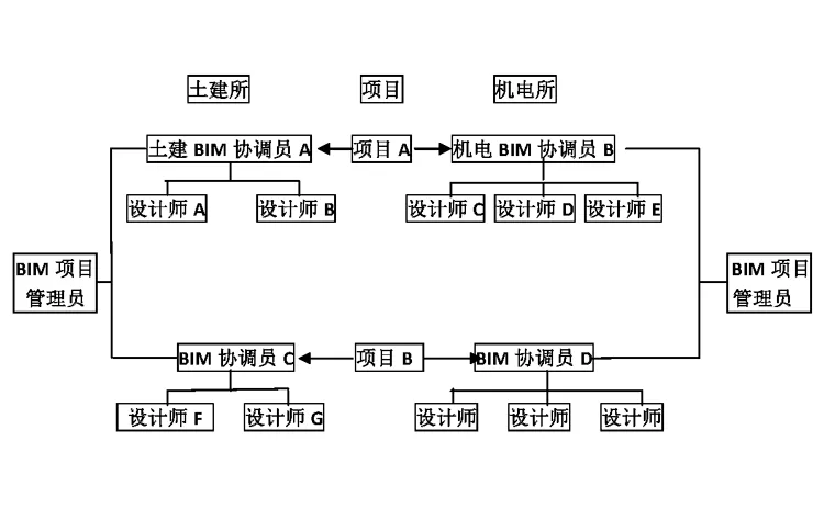
- BIM Project Manager:
The BIM Project Manager promotes BIM projects within the department, assists the project leader in personnel allocation and task division, and determines the overall project schedule with key milestones. They allocate resources to resolve issues and oversee annual BIM tasks within the department. It is recommended that the department head assume this role.
Training Requirements: Attend BIM conceptual introduction training and company BIM process and standard training.
- BIM Coordinator:
Responsible for promoting and supervising BIM standard implementation among team members for individual projects, and providing necessary family libraries. The BIM Coordinator offers complete technical support throughout the project, submitting unresolved issues in reports to the BIM technical team. They manage archiving and organization of all project phases.
Training Requirements: Participate regularly in BIM technology training and company BIM process and standard training. Personnel should be relatively fixed and registered with the BIM technical team.
- Ordinary Designer:
Uses BIM technology to complete design tasks, implements BIM standards, and cooperates with BIM coordinators for project archiving and organization.
Training Requirements: Complete BIM beginner and project phase training, and attend company BIM process and standard tutorials.
3.2 BIM Implementation Process
The BIM implementation process varies depending on the required project execution depth. The basic stages include Depth 1 and Depth 2 processes, with Depth 3 to be supplemented accordingly.
3.3 Quality Objectives and Control
According to the document “XXXXXXXXXXXXXX”, our BIM implementation goals are divided into three levels:
- Depth 1: XXXXXX
- Depth 2: XXXXXX
- Depth 3: XXXXXX
Each department selects projects and corresponding depth requirements based on project specifics.
To standardize process execution, ensure quality control, monitor project progress, and clarify departmental responsibilities, the BIM coordinator must complete the following forms at key milestones:
- Early project stage: “XXXXXX-01-BIM Project Application Document”
- When architecture submits funds: “XXXXXX-02-BIM Collaboration Strategy Record”
- Mid-term verification: “XXXXXX-03-BIM Project Collision Checklist”
- Submission of results: “XXXXXX-04-BIM Project Acceptance Application Form”
- Project Q&A documentation during execution: “XXXXXX-05-BIM Project Q&A Record Form”
4 • Principle of Collaboration
4.1 Workset Usage Principles
- Worksets should be created and subdivided appropriately, assigning each element to a specific workspace.
- Only necessary worksets should be opened.
- The central file must never be opened directly; only local copies of the model should be used.
- The BIM coordinator coordinates synchronization frequency between all team members and the central file, typically every 1 to 2 hours.
- REVIT central and linked file names must be in English, following naming conventions detailed in Section 5.4; Chinese names are prohibited.
- When closing REVIT, designers should retain their work and permissions. Any permission release must follow the BIM coordinator’s unified guidance.
4.2 Interdisciplinary Collaboration Principles
Two collaboration methods are available on the REVIT platform: workset collaboration and link collaboration. The choice depends on project complexity.
4.2.1 Workset Collaboration Mode
For projects under 20,000 square meters, with fewer than 100 drawings and no more than 5 designers, workset collaboration is recommended:
- The BIM coordinator creates a central file, sets project information, elevation, and grid, and establishes a workspace for each designer.
- Each designer copies the central file locally to create their work copy.
- The architecture team creates floor plans based on elevation and sets views to Preliminary Construction.
- Other disciplines create their professional drawings by copying with details, adjusting views to their respective types.
- Each designer works within their assigned workspace on models and drawings.
4.2.2 Link Collaboration Mode
For projects larger than 20,000 square meters with multiple designers per discipline, link collaboration between teams is used:
- Under BIM coordinator guidance, each discipline creates its own central model.
- The architecture team creates a grid and elevation positioning file named AXIS.RVT.
- AXIS.RVT is linked into each discipline’s model, aligning origin to origin and copying elevation and grid by monitoring copy.
- Professional leaders create worksets for each designer within their discipline’s central model.
- Designers create local copies and work on their assigned worksets.
- The BIM coordinator is responsible for overall model assembly and review.
4.2.3 Integrated Collaborative Mode
Projects exceeding 50,000 square meters require link collaboration with further subdivision between specialties:
- Refer to Section 4.2.2 for the basic process.
- Models exceeding 100 MB should be split via interdisciplinary collaboration.
4.3 Intra-disciplinary Collaboration Principles
- Divide models by floor, such as towers and podiums.
- Split according to structural systems and along expansion joints.
- Separate external curtain walls from internal functional areas.
- Divide by systems.
- Divide by region.
4.4 Collision Detection Requirements
After completing each discipline’s model, clash detection must be performed following these guidelines, with the “XXXXXX-BIM Project Collision Check Form” completed accordingly:
- BIM coordinators assemble discipline models and evaluate their completeness.
- Export models to Navisworks for clash detection and record results.
- Discipline teams revise models, perform secondary Navisworks checks, and update records.
- Submit the “XXXXXX-03-BIM Project Collision Checklist”.
- Model evaluation and clash check criteria are detailed in the table below.
| Model Integrity Requirements | Modeling Standards | Design Indicators | Model Coordination | |
| Architectural Model | 1. Include all necessary building components. | 1. Use correct objects for building components. | 1. Include accurate room information. | 1. No significant conflicts between objects. |
| 2. Include all defined floors. | 2. Component types comply with agreements. | 2. Define height including ceiling space. | 2. No clashes between architectural and structural models. | |
| 3. Model building components and spaces on each floor separately. | 3. No extra components. | 3. Room size and height match the model. | ||
| 4. No duplicate or overlapping components. | 4. Spaces do not overlap. | |||
| 5. Components are associated with the respective floor. | 5. All spaces have unique identifiers. | |||
| 6. Models and components include necessary attributes. | ||||
| 7. Classification and naming meet composite specification requirements. | ||||
| Structural Model | 1. Include all necessary structural components. | 1. Use correct objects for structural components. | 1. Columns and beams accurately express displacement relationships. | 1. No significant conflicts between objects. |
| 2. Include all defined floors. | 2. Component types comply with agreements. | 2. Accurate elevation relationships between beams and slabs. | 2. No clashes between architectural and structural models. | |
| 3. Model building components and spaces on each floor separately. | 3. No extra components. | 3. Include openings reserved for mechanical and electrical systems. | 3. Openings do not conflict with structural components. | |
| 4. No duplicate or overlapping components. | ||||
| 5. Components are associated with the respective floor. | ||||
| 6. Models and components include necessary attributes and coding information. | ||||
| 7. Classification and naming meet composite specification requirements. | ||||
| Mechanical and Electrical Model | 1. Include all required mechanical and electrical equipment components. | 1. Use correct objects for components. | 1. Components arranged at appropriate elevations. | 1. No significant conflicts between components. |
| 2. Include all defined floors. | 2. Components belong to correct systems. | 2. No internal conflicts within mechanical and electrical disciplines. | ||
| 3. Model building components and spaces on each floor separately. | 3. Use regulated colors for electromechanical systems. | 3. No conflicts between mechanical and electrical disciplines. | ||
| 4. No extra components. | 4. No conflicts between mechanical/electrical equipment and structural components. | |||
| 5. No duplicate or overlapping components. | 5. Adequate space for handling, installation, and maintenance of equipment. | |||
| 6. Components are associated with the respective floor. | ||||
| 7. Models and components include necessary attributes and coding information. | ||||
| 8. Classification and naming meet composite specification requirements. | ||||
| Integrated Coordination Model | Meets content and depth requirements of all professional models. | 1. Complies with all professional modeling standards. | 1. No conflicts between vertical shafts and electromechanical systems. | |
| 2. Consistent with the latest design version. | 2. Horizontal reserved openings do not conflict with mechanical and electrical equipment. | |||
| 3. Each professional model shares a unified design origin and coordinate system. | 3. No conflicts between suspended ceilings and mechanical/electrical equipment. | |||
| 4. No conflicts between mechanical/electrical equipment and columns, beams, or slabs. |
5 • Project Standards
5.1 Template File Usage Principles
Our company’s template files consist of three parts:
- Basic template
- Collaborative template
- Professional template
The basic template contains company drawing standards, frames, labels, line styles, symbols, and other unified drawing standards. The collaborative template includes drawing layouts and project browser settings tailored to each collaboration mode. The professional template provides commonly used types, families, view templates, and filters for various disciplines.
When initiating a project, the BIM coordinator assembles the basic, collaborative, and professional templates into discipline-specific templates according to the collaboration mode and stores them in designated folders.
5.2 Family Library Usage Principles
- Family library management prioritizes convenience and accuracy to facilitate designer use.
- Production and review of family files follow unified standards to ensure quality.
- Family files are accessible on company-level platforms for projects only, preventing unauthorized downloads and protecting intellectual property.
- Due to the absence of a mature family library management platform, temporary application download methods are in place.
[Release] The company-level family database regularly publishes the latest family file directory on the company information platform for designer review. Searchable information includes family name, category, brief description, and preview images, as illustrated below.


Must log in before commenting!
Sign Up