The preliminary preparation and scheme design phase of the Haping Road subway station project is crucial due to its large scale and numerous associated risks. Implementing BIM technology early in the engineering process helps break down barriers between different disciplines during the design phase, resolving information silos and enabling the selection of the optimal construction technology plan.
Project Layout and Risk Identification
The Haping Road subway station is situated at the intersection of a busy urban main road, surrounded by closely packed buildings and critical pipelines. Given the station’s “ultra deep and ultra wide” dimensions, the construction process faces multiple risk factors that pose significant safety hazards during later stages.
BIM technology’s visualization capabilities allow for a comprehensive, three-dimensional display of the station’s site layout and surrounding risk sources. This visualization not only highlights potential hazards but also enables construction personnel to intuitively understand the project’s characteristics and current status.
Specifically, the station area contains five environmental level 1 risk sources and three engineering level 1 risk sources. Using Revit software, a 3D model incorporating the station layout, main structures, and major risk sources was developed. This model visually represents nearby important buildings, drainage and water supply pipelines, and existing structures, providing an intuitive overview of the project and critical risk areas. The risk source model is illustrated in Figure 1. Additionally, the overall project model is imported into a BIM management platform to locate and label risk sources, aiding in the planning of excavation and safety management during construction.
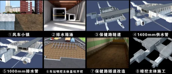
Figure 1: Environmental and Engineering Risk Source Model Diagram
Plan Optimization and Design Coordination
Creating a detailed and efficient construction design plan is the most critical aspect of the engineering process. For a complex project like the Haping Road subway station, design plans require multiple rounds of refinement and optimization to ensure feasibility. Traditionally, modifying errors in design plans involves manually updating all related drawings, which is time-consuming and labor-intensive.
BIM’s optimization capabilities provide a significant advantage during the design phase. This technology not only highlights the value of high-quality design but also facilitates the identification of the most efficient construction plan. The construction scheme for this project includes deep foundation pit engineering, station transfer channel engineering, and underground bridge renovation.
Initially, Revit software is used to build three-dimensional solid models for these three projects. Construction plans are then optimized based on safety, scheduling, cost, and technical requirements, increasing accuracy and relevance. Thanks to the logical relationships within the BIM model, any modifications automatically update all related drawings and models.
Key areas of optimization include selection of enclosure structures, excavation sequencing, and support structure design for deep foundation pits and station transfer passages. The goal is to identify the safest construction methods while minimizing cost and duration. Adjustments are made by varying enclosure types and sizes, as well as the material composition and layout of support structures.
Figures 2 and 3 present models of the support structures for the deep foundation pit and transfer channel, respectively. For the underpass bridge renovation, the project focuses on establishing the removal sequence of retaining piles, specifying concrete types and quantities for reinforcing walls and the bottom plate, and continuously optimizing the reinforcement plan through BIM coordination. Figures 4 and 5 illustrate the underpass bridge’s structure before and after renovation.
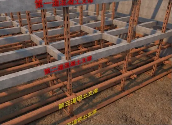
Figure 2: Model Diagram of Deep Foundation Pit Engineering Support Structure
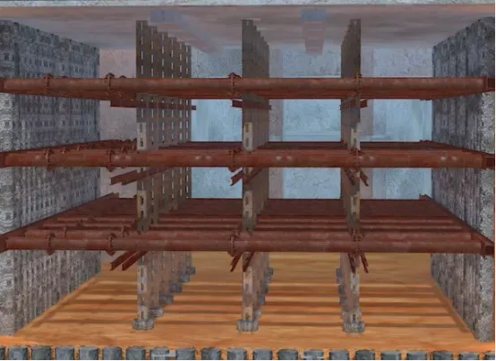
Figure 3: Model Diagram of Support Structure for Station Transfer Passage
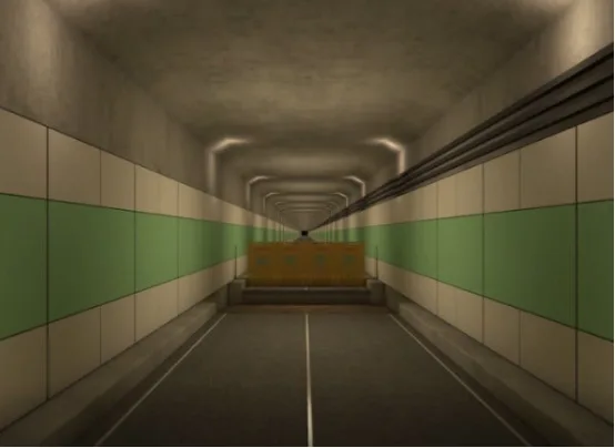
Figure 4: Structural Model Diagram of Underpass Bridge Before Renovation
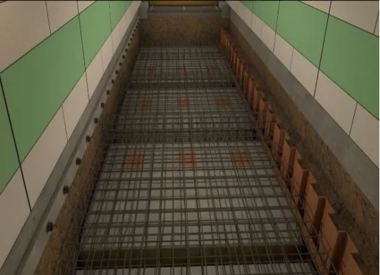
Figure 5: Structural Model of Underpass Bridge After Renovation
Collision Detection and Interdisciplinary Coordination
Subway station construction sites are typically confined spaces, making construction organization and management exceptionally challenging. Safety incidents often arise from spatial conflicts between construction elements and clashes between different trades. Proper coordination of workspace and construction sequences is essential to avoid errors, omissions, and collisions during construction.
Collision detection, a core function of BIM software, effectively identifies spatial conflicts among pipelines, components, and equipment. After preliminary construction scheme development, collision checks are conducted to detect potential issues.
This project uses Navisworks software to model the physical shapes of components and equipment, building an interactive 3D excavation simulation and support system model. The software dynamically simulates construction stages for deep foundation pits and transfer channels, allowing observation of equipment-support interactions and structural stress characteristics. This helps optimize the support system further.
Special attention is paid to the spatial relationships of critical pipelines and large machinery. For foundation pit excavation, ensuring adequate space for mechanical equipment and personnel is vital—considering factors like excavator rotation radius, tower crane operating paths, and worker movement zones.
Continuous collision detection with Navisworks identifies collision points, primarily between excavation machinery and support structures. By adjusting support structure spacing and iterating design modifications, the project achieves a “zero collision” model that meets professional standards.
Figures 6 and 7 illustrate the spatial positioning of machinery relative to support structures in the deep foundation pit and transfer channel engineering, respectively.
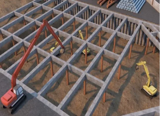
Figure 6: Position Model of Deep Foundation Pit Machinery and Support Structure
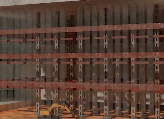
Figure 7: Mechanical and Support Structure Position Model of Transfer Channel
Collaborative Review and Design Briefing
The success of any engineering project depends heavily on the design and construction plans. Finalizing the construction plan requires consensus among the construction company, project owner, and design teams, along with coordination among geotechnical, structural, mechanical, and electrical professionals.
BIM software, such as Revit, facilitates rapid generation of engineering plans, sectional views, and support structure drawings for deep foundation pits and station transfer passages after each excavation phase. All drawings include precise dimension annotations, enabling all stakeholders to gain a detailed understanding of the project.
During professional reviews, technicians analyze design issues using BIM-exported drawings, collision detection reports, and key construction challenges. Each discipline discusses technical solutions based on structural models and updates their parts of the engineering model in real time using BIM visualization.
Through repeated evaluation and discussion, the team finalizes a technical solution that ensures construction safety. BIM’s digital 3D modeling allows all parties to jointly review and assess the construction plan on a unified platform, ensuring that changes by any discipline are consistently reflected across the project files. This streamlines the review and design briefing process, significantly enhancing communication efficiency among professionals and stakeholders, improving design and construction quality, and making the preparation stage more efficient.
Zhao Zhicheng (Harbin Institute of Technology)
For learning and communication purposes only. Copyright belongs to the original author. If there is any infringement, please contact us for removal.


Must log in before commenting!
Sign Up