B-Grade Slope Creation:
To create a B-grade slope, start by adding auxiliary detection points to determine the grading level. Replace point p2 with an auxiliary point AP1 and set it as the slope to the surface, based on a single-stage slope. The initial step involves using detection points to evaluate the slope. The numerical height at the slope’s foot point helps decide whether multi-level slope creation is necessary, as illustrated in Figure 1.
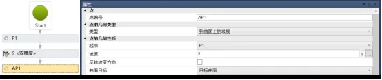
Figure 1: Creating Auxiliary Points
Next, add slope parameters by creating a slope height variable H1 in the input/output window. Set its type to double precision, defaulting the slope height to 3 meters, and label it as “Slope Height,” as shown in Figure 2.
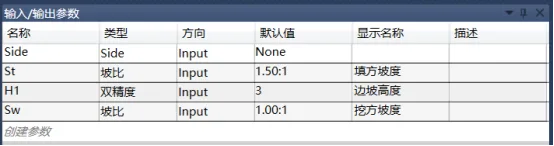
Figure 2: Adding Slope Conditions
Determine the grading level by adding judgment commands within the toolbox workflow. Set criteria using VB language to compare the height difference between the starting point and the detection point against the slope height variable H1. If the height difference is less than H1, a single-stage slope suffices; if greater, multi-level slopes must be configured, as depicted in Figure 3.
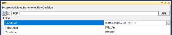
Figure 3: Expression for Determining Grading Levels
For single-stage slope conditions, add point p2 at one end of the slope within the flowchart’s judgment condition, aligning its position with the auxiliary point AP1. Then, create a connection from p1 to p2 to complete the single-stage slope setup. Dragging the surface object with a height difference within 3 meters displays a slope preview, as shown in Figure 4.
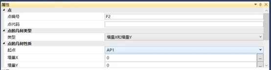
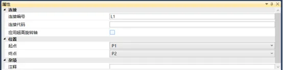
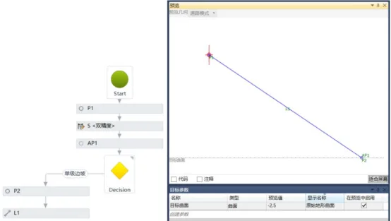
Figure 4: Setting Up Multi-Level Slopes for Single-Stage Slopes. Select the sequence in the left toolbox workflow, which will be used for excavation and fill determination.
Place the defined variable S in the sequence and add a new height variable HV under the judgment of S, as shown in Figure 5.
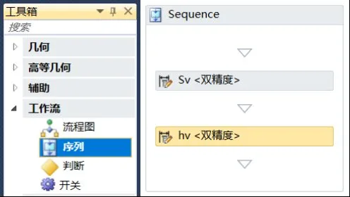
Figure 5: Sequence Setup
Define a height variable with a VB language expression to correct the negative sign generated by positive and negative judgments, as illustrated in Figure 6.
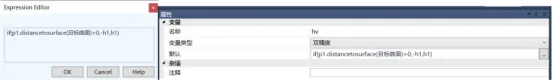
Figure 6: Expression for Height Variables
Set the first level of the multi-level slope by adding point p2 on the right side of the multi-level slope judgment condition. Define this point as a slope with a vertical increment y, starting at p1 with slope s and increment y as hv. Enable the option to add a connection to the starting point and name it L1, as shown in Figure 7.
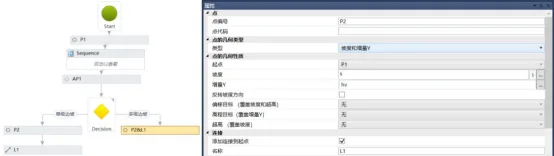
Figure 7: First Level Slope Setup
Configure the platform by increasing the platform width and slope parameters, as shown in Figure 8.
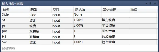
Figure 8: Setting Platform Parameters
Add a platform slope variable within the sequence to offset the negative sign of the platform slope, as demonstrated in Figure 9.
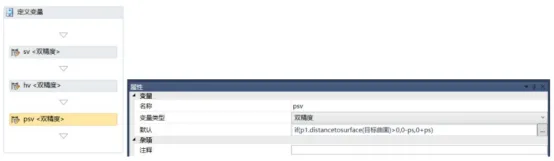
Figure 9: Expression of Platform Slope Variables
Determine the positional relationship between the platform slope and the original terrain surface. Add a new flowchart and include auxiliary point AP2, setting its type to slope with an increment in the x direction. The slope variable is psv, and the increment x corresponds to the platform width pw, as shown in Figure 10.
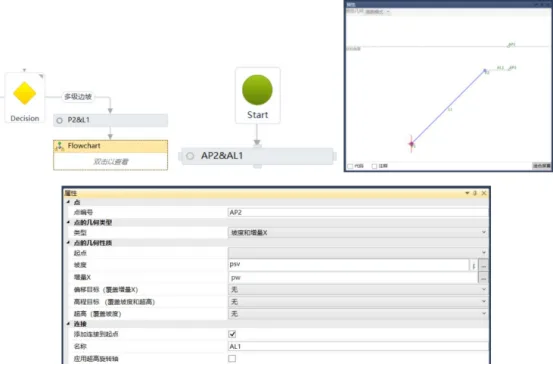
Figure 10: Determining the Relationship Between Platform and Surface Position
Establish the full width of the platform slope or its intersection endpoint with the curved surface. Add a judgment command under auxiliary point AP2, setting it to true until the surface ends and false for the full width. Use a VB language expression in the editor to check whether the test slope point is above or below the surface by multiplying the distances from points p2 and AP2 to the surface, as shown in Figure 11. This facilitates subsequent slope or end slope commands.
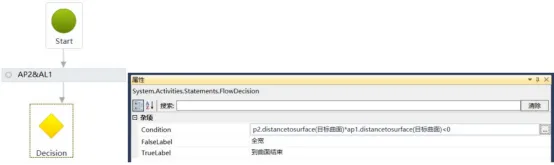
Figure 11: Expression for Platform Slope Endpoint
When the platform intersects the surface, add a slope command to complete the slope. If the judgment condition is true, add a new point p3 on one side, set its type as slope to the surface, starting at p2 with slope variable psv, and add a connection to the starting point, as seen in Figure 12.
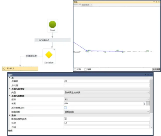
Figure 12: Platform Grading to End
To continue sloping the platform’s full width, add point p3 with type slope and increment x. Start at p2 with slope variable psv and increment x as platform width pw. Add a connection to the starting point, as shown in Figure 13.
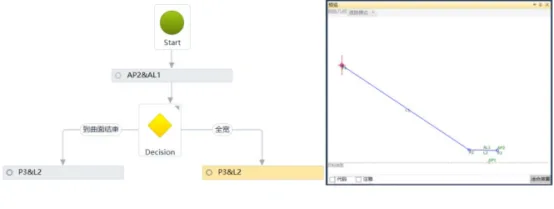
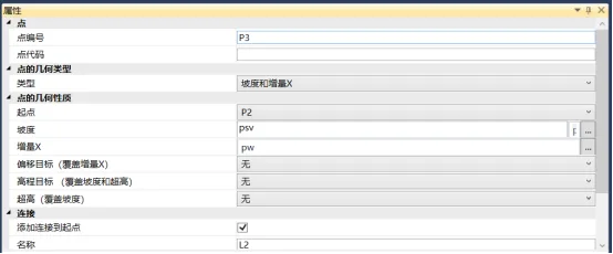
Figure 13: Continuing the Platform Slope
Repeat this process to create second and third level slopes, as demonstrated in Figure 14.
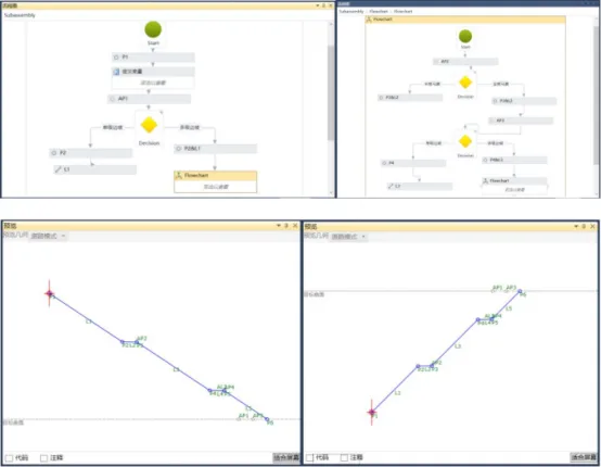
Figure 14: Secondary and Tertiary Slopes
When generating a road model, it is essential to vertically connect basic elements sharing the same code. Connect points vertically to create feature lines, link feature lines to form surfaces, connect surfaces to generate model entities, and assemble these connections to build a complete road model object. Therefore, assign codes to all points, connections, and shapes.
After finishing the custom multi-level slope component, save it as a .pkt file and import it into Civil 3D. Open the Tools tab in Civil 3D and add the custom component .pkt file to the appropriate component directory for easy access during assembly modeling, as shown in Figure 15.
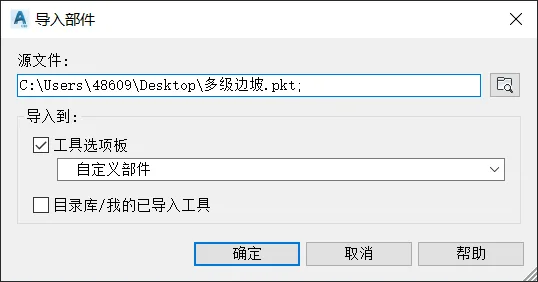
Figure 15: Importing Components
Note that the road model created using the component editor’s custom .pkt file requires the original .pkt file to be present in the corresponding directory when opened. Without it, the road model cannot be edited or modified, thereby enhancing the confidentiality of the design data.
Author: Yang Long (Jilin University of Architecture)
For learning and communication purposes only. Copyright belongs to the original author. If any infringement occurs, please contact us for removal.


Must log in before commenting!
Sign Up