In Civil 3D, the slope gradient for each level in the built-in multi-level slope component is uniform, and you cannot edit or customize the slope values individually. However, in real-world road engineering projects, the gradient often varies between levels. This article demonstrates how to create complex multi-level slopes with different gradients using Civil 3D.
Step 1: Creating a Single-Stage Slope
First, create the target surface. In the target parameter dialog box at the bottom right, click the Create Parameter command. Set the parameter name to Target Surface, type to Surface, preview value to -20, display name to Original Terrain Surface, and enable the preview option, as shown in Figure 1.
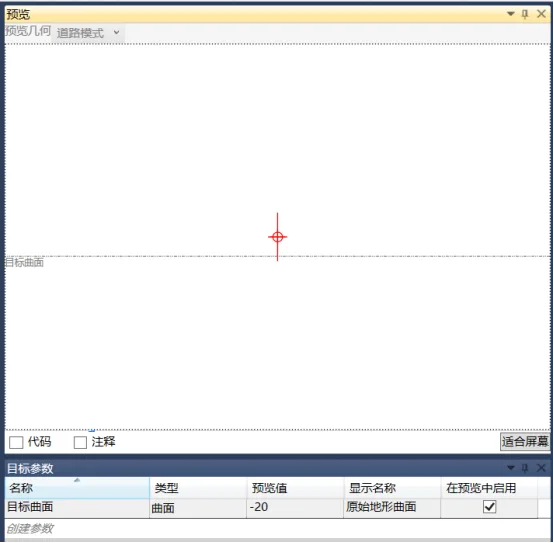
Figure 1: Creating a Surface Target
Next, create the first point in the flowchart. In the property dialog box, set its starting point as the origin, as illustrated in Figure 2.
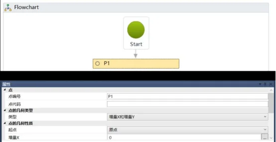
Figure 2: Creating Origin in the Flowchart
Then, in the input/output parameter dialog box at the lower right, click Create Parameter to add input and output parameters for cut and fill slopes. Assign different slope ratios to these parameters, as shown in Figure 3.
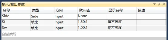
Figure 3: Creating Input and Output Parameters for Filling and Excavating Slope
Access the Define Variables command from the Miscellaneous toolbar, as shown in Figure 4.
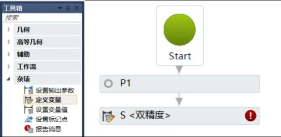
Figure 4: Defining Variable Commands
Select the defined variable object, set its name to S, and choose double precision as the variable type in the property dialog box below, as depicted in Figure 5.

Figure 5: Variable Attribute Settings
For variable control, use the default VB function language. Common VB functions available are shown in Figure 6.

Figure 6: VB Language Functions
Within the expression editor, use an IF statement to determine whether the distance from the location to the surface is positive or negative to control variable calls, as shown in Figure 7.
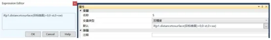
Figure 7: Surface Judgment Expression
Create a new slope endpoint named p2. In the property dialog box, set the point type to Slope to Surface, set the starting point to p1, input the slope value as the variable S, and specify the target surface. Make sure to check the option to connect this point to the starting point, as shown in Figure 8.
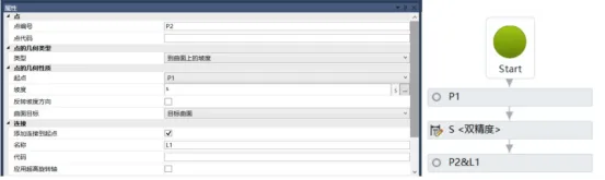
Figure 8: New Slope End Point
Now, by dragging the top and bottom positions of the target object in the preview window, you can visualize the slope gradients for both cut and fill conditions, as illustrated in Figure 9.
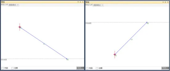
Figure 9: Preview of Single-Stage Filling and Excavation Slope Components
Yang Long (Jilin University of Architecture)
For learning and communication purposes only. Copyright belongs to the original author. If any infringement occurs, please contact us for removal.


Must log in before commenting!
Sign Up