Pressure pipelines differ from gravity pipelines in that they lack structural components and consist primarily of pressure pipes, fittings, and equipment accessories, as illustrated in Figure 1. These elements can be linked to routes, profiles, and surfaces. The pipe fittings typically include tees and elbows, while equipment accessories mainly consist of valves.
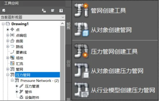
Figure 1: Pressure Pipeline Components
The process of creating a pressure pipeline network closely resembles that of a gravity pipeline network. Both require the setup of a pipeline catalog and parts list before starting. Typically, you either use the layout toolbar or create a pipe network from linear objects.
Pressure networks rely on upstream pressure to drive flow through the pipeline. In a three-dimensional spatial layout, unlike gravity flow pipelines, pressure networks are not influenced by elevation. Therefore, there is no need to define special pipeline rule sets, and vertical pipelines can be created without restrictions. Connections in gravity pipelines are made through structural elements, while in pressure pipelines, connections are established via fittings or equipment accessories.
1) Pre-Creation Settings
A. Specify the pressure network catalog.
B. Create a parts list for the pressure network.
2) Creating the Pressure Pipe Network
To create the pipeline network, use the dedicated pressure network creation tools:
Click the pressure network creation tool located under the pipeline command in the Common tab. In the pop-up dialog box, configure the styles for the parts list, associated objects, route objects, pressure pipeline fittings, and equipment accessories, as shown in Figure 2.
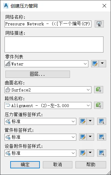
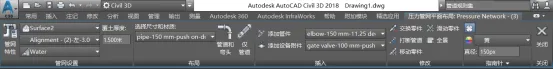
Figure 2: Pressure Network Creation Interface
The pressure pipe network layout tool is located in the upper functional area. Simply click on the desired locations within the plan view to lay out the pipe network. The vertical elevation of the pressure pipeline network can be set either by specifying the soil cover thickness relative to a chosen surface or by directly inputting elevation values during layout.
After selecting the pressure pipe network, add the necessary fittings and equipment accessories. Specify their properties such as specifications, sizes, and materials to complete the pressure network creation, as depicted in Figure 3.
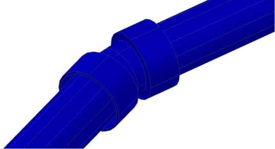
Figure 3: Partial Pressure Network Layout
Creating a Pressure Network from Existing Objects
You can also create a pressure network by converting existing objects:
Use the “Create Pressure Network from Objects” command found under the Common tab. Select the graphic object and confirm the flow direction. Then, configure the parts list and surfaces within the pop-up dialog box, as shown in Figure 4.
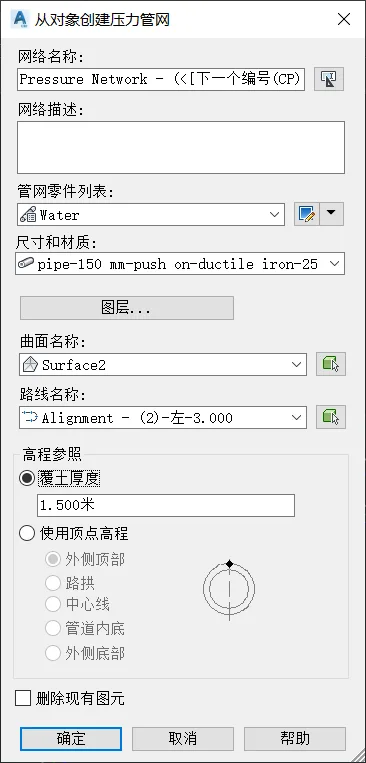
Figure 4: Creating a Pressure Network from Objects
If you use soil cover thickness as the elevation reference, the pipeline network’s vertical elevation will maintain the relative values according to the specified surface. Alternatively, if vertex elevation is used as the reference, the vertical design elevation at the pipeline’s endpoints will correspond exactly to the specified design elevation.
Yang Long (Jilin University of Architecture)
For educational and communication purposes only. Copyright belongs to the original author. If there is any infringement, please contact us for removal.


Must log in before commenting!
Sign Up