Civil 3D offers two primary methods for creating pipe networks: using the dedicated pipe network creation tools or generating pipe networks from existing objects, as illustrated in Figure 1.
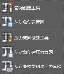
Figure 1: Pipe Network Creation Command
1. Creating a Pipe Network Using the Pipe Network Creation Tool:
Start by selecting the pipe network creation tool located under the common tab in the pipe network commands. A dialog box will appear, allowing you to customize the pipe network parts list, set the target surface, route, and pipe label styles, as shown in Figure 2.
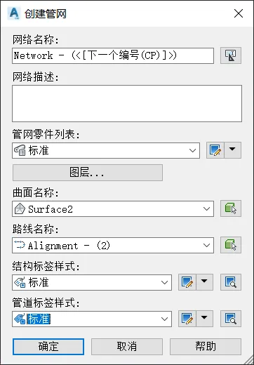
Figure 2: Official Website Dialog Box for Pipe Network Creation
Once confirmed, the network layout toolbar will appear, resembling the toolbars used for creating road routes and profiles. Use this toolbar to specify the required pipes and structural components, and employ its commands to build your pipe network, as demonstrated in Figure 3.

Figure 3: Network Layout Toolbar
This toolbar supports creating both pipes and structures, as well as individual pipe or structure objects. The tool also includes a command to switch the pipeline direction between uphill and downhill, allowing you to adjust the flow direction as needed, shown in Figure 4.
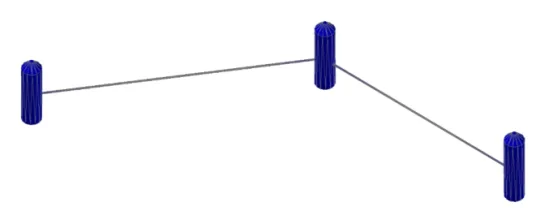
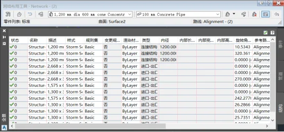
Figure 4: Pipe Network Created Using the Pipe Network Creation Tool
To view and edit detailed information about the entire pipe network, click the pipe network view command located on the right side of the network layout toolbar. This opens the pipe network panorama dialog box for comprehensive management.
2. Creating a Pipe Network from Objects:
You can also create pipe networks from existing objects such as lines, arcs, polylines, 3D polylines, alignments, and feature lines.
Simply select the “Create Pipe Network from Object” command under the common tab, choose your desired object, and specify the flow direction for the new network. In the dialog box that appears, name your pipe network, select the parts list, and configure pipes and structures to be included. Adjust any other settings as needed, then click OK to generate the pipe network, as shown in Figure 5.
Figure 5: Creating a Pipe Network from Objects
Yang Long (Jilin University of Architecture)
For educational and communication purposes only. Copyright belongs to the original author. If any infringement occurs, please contact us for removal.


Must log in before commenting!
Sign Up