The built-in assemblies provided by the software may not always satisfy the complex and diverse demands of various projects. Different projects often feature unique cross-sectional configurations, such as non-shared board structures, asymmetric arrangements, and separated roadbeds. In these cases, it becomes necessary to manually assemble the components into customized assemblies.
To start, click on “Create Assembly” under the “Common Tab Assembly Command”, and then customize the assembly name as shown in Figure 1.
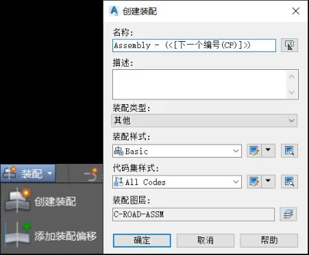
Figure 1: Create Assembly Command
Next, select the basic lane from the basic directory in the tool palette. Click on the designated point, choose the basic components to add to the assembly, and adjust their width, thickness, and slope properties to match the design specifications, as illustrated in Figure 2.
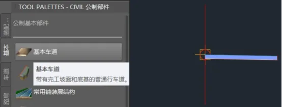
Figure 2: Creating a Basic Lane
Then, add the regular curb and gutter from the city road directory by attaching them to the marker point located at the upper right corner of the roadway. Adjust their parameters to comply with design requirements. Similarly, add the sidewalk to the attachment point at the upper right corner of the ditch, as shown in Figure 3.
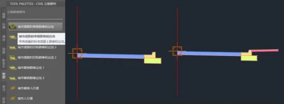
Figure 3: Creating Roadside Ditches and Pedestrian Walkways
Next, use the slope step component from the slope directory and add it to the far right side. For simple roads involving low fills or shallow excavations, you can use the connecting slope components from commonly used catalogs as single-stage slope components, as demonstrated in Figure 4.
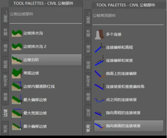
Figure 4: Creating a Slope
After preparing the right-side components, select the baseline and use the Mirror command located in the Modify Components tab. Mirror the right-side components to the left side of the baseline to complete the assembly, as shown in Figure 5.
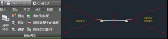
Figure 5: Mirroring to Create a Complete Assembly
In a professional setting, designers can save significant time and effort by accumulating custom assemblies or components for future use. To do this, right-click on the tool palette, select “New Palette”, and name it “Common National Standard Assembly”. Then, drag your custom assembly baseline into this new palette for easy access across future projects, as shown in Figure 6.
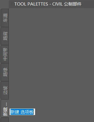
Figure 6: Creating a New Palette
Yang Long (Jilin University of Architecture)
For educational and communication purposes only. Copyright belongs to the original author. If there is any infringement, please contact us to request removal.


Must log in before commenting!
Sign Up