Start by selecting the feature line object, then click the slope creation tool command located on the command bar above, as shown in Figure 1.

Figure 1: Slope Creation Tool Command
In the slope creation tool dialog box, click the first button labeled Set Slope Group to create a new slope group. In the Create Slope Group dialog box, name the slope group, enable the option to automatically create surfaces, and specify the surface styles as illustrated in Figure 2.
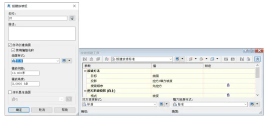
Figure 2: Creating a Slope Group
Next, in the Create Surface dialog box, set the surface type to a triangular mesh surface. Define the surface style and rendering material accordingly, as shown in Figure 3.
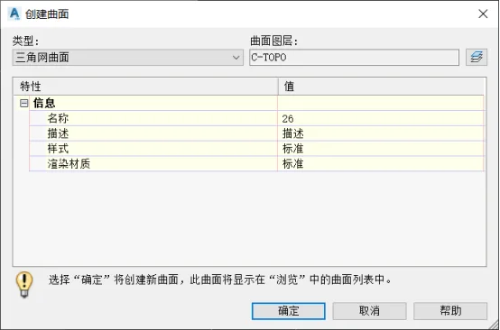
Figure 3: Create Surface Dialog Box
Then, click the second button located at the upper left corner of the Create Slope Tool dialog — Set Target Surface. In the Select Surface dialog box, choose the original terrain surface as the target surface, as depicted in Figure 4.
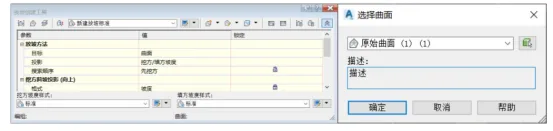
Figure 4: Setting the Target Surface
Next, use the Set Grading Layer command within the Create Grading Tool to assign the layer where the grading model will be placed.
Then, in the Create Slope Standard section, click Set Slope Standard Set to select the slope standard set that includes the new slope method. Choose the appropriate slope standard as your new slope criteria, as illustrated in Figure 5.
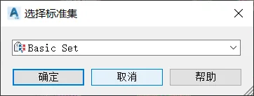
Figure 5: Selection Criteria Set
Now, click the Create Slope command. Follow the prompts on the taskbar to select the feature line object, specify the slope edge (pointing outward), and apply the slope along the entire length by confirming with “Yes”. Proceed to define fill slope and excavation slope parameters, then finalize the slope creation by pressing Enter, as shown in Figure 6.
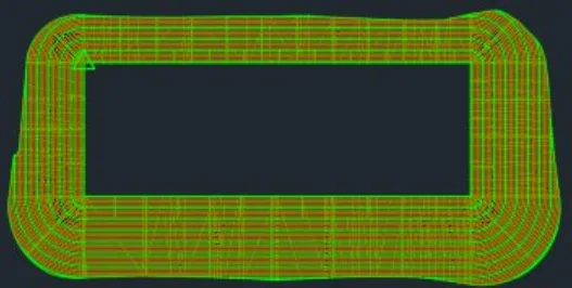
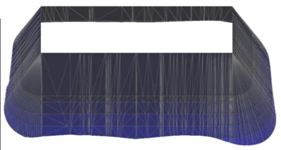
Figure 6: Completed Slope Creation
When viewing the slope object in 3D using the object viewer, you may notice an empty space above the slope. To facilitate earthwork volume calculations, this top region needs to be closed.
To do this, click the Create Fill command found under the Create Slope command. Select the area within the drawing to complete the creation of a closed region. Then, select the slope surface and right-click to view it in 3D perspective within the object viewer. The cavity above the surface will now be closed, as shown in Figure 7.
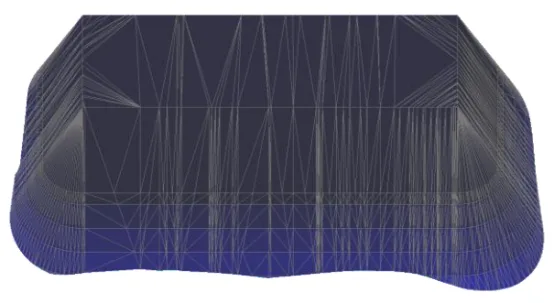
Figure 7: Creating a Closed Top Region on the Slope
Author: Yang Long (Jilin University of Architecture)
For educational and communication purposes only. Copyright belongs to the original author. If there is any infringement, please contact us for removal.


Must log in before commenting!
Sign Up