Civil 3D generates cross-sectional design drawings through a multi-step process. It starts by creating several cross-sections from data sources like road models using sampling lines. Then, it produces a set of cross-sectional drawings via drawing templates, and finally compiles these into the cross-sectional design drawings using the drawing set.
To begin, click the “Create Multiple Views” command found under the commonly used graphics card cross-sectional view, as illustrated in Figure 1.
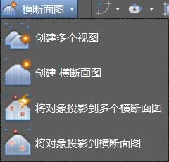
Figure 1: Create Multiple View Command
Next, select the appropriate route and sample line group name. A dialog box will appear for creating multiple cross-sectional views.
The cross-sectional view style dialog is shown in Figure 2.
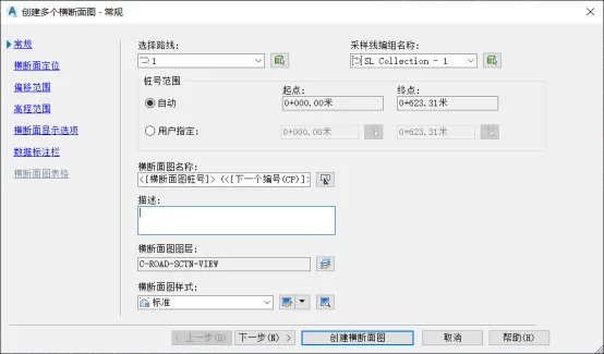
Figure 2: General Dialog Box for Creating Multiple Cross-Sectional Views
Click Next to proceed to cross-sectional positioning settings, as shown in Figure 3. Here, select the drawing model and configure the printing style.
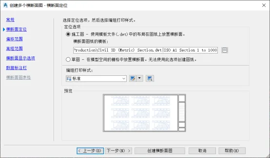
Figure 3: Cross-Section Positioning Settings
Click Next again to open the offset and elevation range settings. Set the horizontal and vertical ranges that will define the extent of the cross-sectional view, as shown in Figure 4.
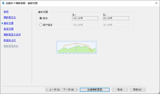
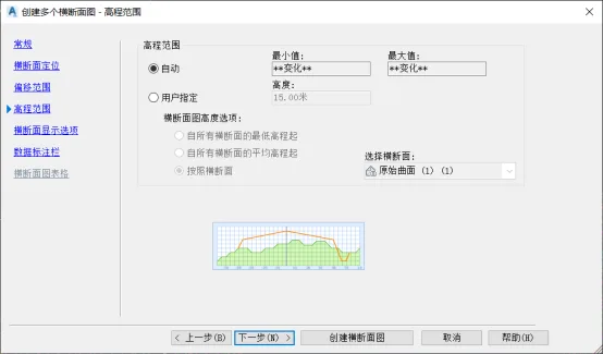
Figure 4: Offset and Elevation Range Settings
Then, configure the cross-sectional display options by selecting the original terrain surface and road model entities, as shown in Figure 5. (Design surfaces can also be included here.)
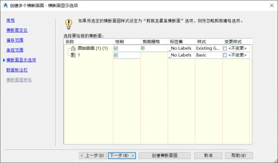
Figure 5: Cross-Section Display Options
Next, set up the cross-sectional data annotation column by selecting the annotation column set and defining its properties, as shown in Figure 6.
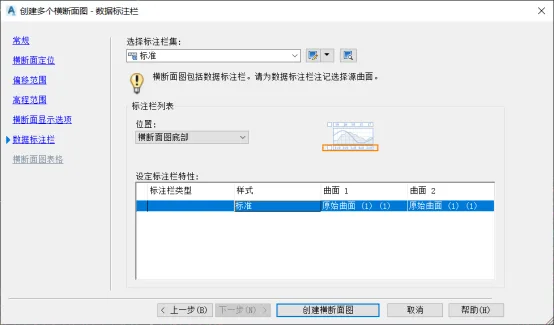
Figure 6: Data Annotation Column Settings
Finally, click to create the cross-sectional view and complete the cross-sectional design drawing, as shown in Figure 7.
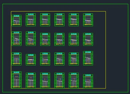
Figure 7: Completed Cross-Sectional Design Drawing


Must log in before commenting!
Sign Up