Civil 3D offers various point representation styles, including green vegetation, street lighting, transportation facilities, and more. These can be inserted onto road surfaces by setting the point style to the corresponding structural style. Structures of the same type are grouped under the same point group. After placing them on the road model, engineering quantities can be easily calculated by querying the point group information or selecting similar objects.
The cross-sections of elements such as side flat stones and side ditches in road models are fixed and unchanging. When creating cross-sectional assemblies, codes for these components are defined separately. Once the road model is generated, specific feature lines can be created from these component codes. These feature lines conform to the three-dimensional twists of the road model, following its horizontal and vertical alignments. By querying the feature line data, both the projected length on the two-dimensional plane and the actual length in three-dimensional space can be obtained.
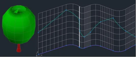
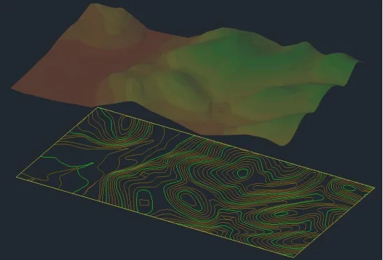
Figure 1: Schematic diagram illustrating points, lines, and surfaces
According to specifications, site clearance measurements should be based on horizontal projected areas. However, for projects with significant terrain variations, these calculations often differ substantially from actual quantities. To achieve more accurate clearing volume estimates, the three-dimensional surface area within the roadbed’s excavation boundary should be measured.
Furthermore, since slope lines intersect the original terrain as irregular three-dimensional polylines, the actual slope protection surfaces consist of two-dimensional surfaces with irregular edges along the slope foot grooves. Using Civil 3D’s surface tools, these surfaces can be cut based on boundary lines to precisely calculate both the projected area and the actual area of irregular 2D and 3D surfaces within the project limits. Figure 1 demonstrates the point styles, 3D curves and their 2D projections, as well as 3D surfaces with their corresponding 2D projections.


Must log in before commenting!
Sign Up