Source: Railway BIM Alliance
By leveraging BIM technology’s strengths in visualization, multidimensional modeling, and collaboration, complex challenges in tunnel engineering design can be effectively addressed.
Approximately 75% of China’s terrain is mountainous or steep hills, with major national railway routes often traversing these regions. Bridge and tunnel engineering is not only a critical technical solution for route selection in difficult terrains but also a key challenge in trunk line design. While traditional 2D design methods suffice for conventional tunnels, they fall short in expressing complex portal structures, 3D intersections for disaster prevention and rescue channels, and multi-disciplinary interface connections due to limited expressiveness, poor information transmission, and low integration.
The successful adoption of BIM in construction has inspired its application in railway tunnels. Building on research and practical experience in railway tunnel BIM design, and using Bentley’s OpenRail Designer (ORD) platform, a systematic study was conducted on BIM forward design for high-speed railway tunnel engineering. A standard system and parametric family library tailored for the design phase were established. Utilizing secondary development technologies, a BIM forward design system aligned with tunnel design processes was developed. This system supports functions such as contour mechanics analysis, parametric data storage, reference drawing design, construction site scheme design, detailed design, engineering quantity calculation, and automated generation of 2D drawings and 3D models, achieving preliminary BIM forward design for high-speed railway tunnels.
Overall Planning
To implement BIM forward design for high-speed railway tunnels, compatibility with existing documents—such as surveys, geological data, and route plans—is essential, alongside alignment with traditional design practices. BIM deliverables must comply with standards issued by the Railway BIM Alliance, and 2D drawings should adhere to industry benchmarks like the “Railway Engineering Drawing Standard” and enterprise technical documentation requirements.
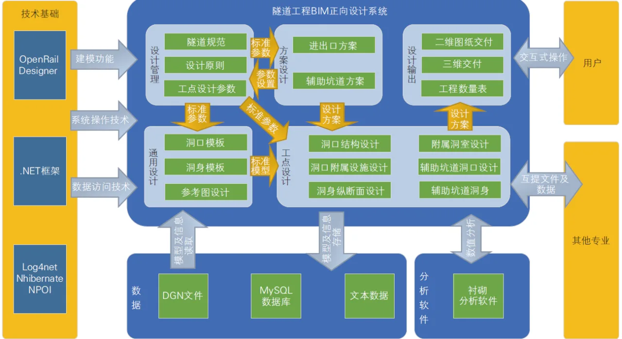
Drawing on years of research and practical experience, a technical roadmap was developed to create a tunnel BIM forward design system based on ORD. This system uses the BIM standard system and parameterized family library as a foundation and is built on the popular .NET framework, supported by Log4NET, NHibernate, and NPOI for auxiliary functions. The system’s main design capabilities are divided into six modules: design management, general design, tunnel body design, portal design, special design, and design output. It offers an intuitive interface and supports efficient data exchange across disciplines. The architecture of this forward design system is illustrated below.
Standard System Development
The Ministry of Housing and Urban-Rural Development of China has prioritized BIM promotion, issuing key documents such as the 2014 “Opinions on Promoting Construction Industry Development and Reform” (Jian Shi [2014] No. 92) and the 2016 “Outline for IT Development in the Construction Industry (2016-2020)” (Jian Zhi Han [2016] No. 183). The Railway BIM Alliance has also released 16 standards and guidelines, including:
- T/CRBIM 001-2014: Guidelines for Railway Engineering Entity Structure Decomposition
- T/CRBIM 002-2014: Classification and Coding Standards for Railway Engineering Information Models
- T/CRBIM 003-2015: Data Storage Standards for Railway Engineering Information Models
Building on BIM promotion experiences and industry needs, China Railway Group Limited developed a series of guiding documents, such as the “China Railway BIM Application Implementation Guidelines,” which have been continuously refined through practical projects. Between 2016 and 2020, China Railway Group advanced BIM research and applications in urban rail transit, achieving significant breakthroughs and establishing a BIM standard system for urban rail transit engineering construction.
In March 2021, the National Railway Administration released the “Unified Standard for Railway Engineering Information Model,” effective June 2021. These standards and guidelines, along with project-based verification, have played a vital role in elevating BIM technology adoption in the railway sector, enabling standardized management and advancing digital transformation in engineering construction.
Guided by documents from China Railway Group Corporation, Railway BIM Alliance, and others, and informed by urban rail transit BIM applications and industry practices, a BIM standard system for railway tunnels has been formulated. This system comprises four levels: outline, guidelines, standards, and manuals. It standardizes architecture, coding, application workflows, and deliverables, creating a comprehensive BIM forward design standard for tunnels.
The outline defines basic regulations, guiding principles, and scope. Guidelines present technical strategies and forward design processes. Standards specify detailed design stages, data encoding, modeling, and information delivery. Manuals provide step-by-step instructions for planning, preliminary, technical, construction drawing, and detailed designs, enabling standardized workflows. This BIM forward design standard system for tunnels has seen practical application in complex mountainous railway trunk lines such as the Xikun Line, Chongqing Kunming Line, and Chengdu Chongqing Middle Line.
Establishment of Parameterized Family Library
A standardized and parameterized family library prevents redundant modeling, reduces workload, and enhances modeling efficiency and consistency. When developing this library, considerations include high-speed railway tunnel design requirements, construction methods, post-construction handover, and additional data needed during modeling to support quantity calculations, drawing production, and design deliverables.
According to Railway BIM Alliance standards, the family library is classified by tunnel structural components into four main categories: tunnel portal, tunnel body, interface, and special structures.
Tunnel Portal
Reference diagrams and site construction drawings of tunnel portals are analyzed to extract key geometric parameters for parametric modeling. Using ORD’s secondary development, these parameters feed into a tunnel portal generation algorithm, enabling parametric modeling and rapid instantiation of portal models along actual routes. Currently, the portal family library includes types such as brimmed slant cut portals, double ear wall openings, and pile column portals.
Brimmed slant cut tunnel portal
Tunnel Body
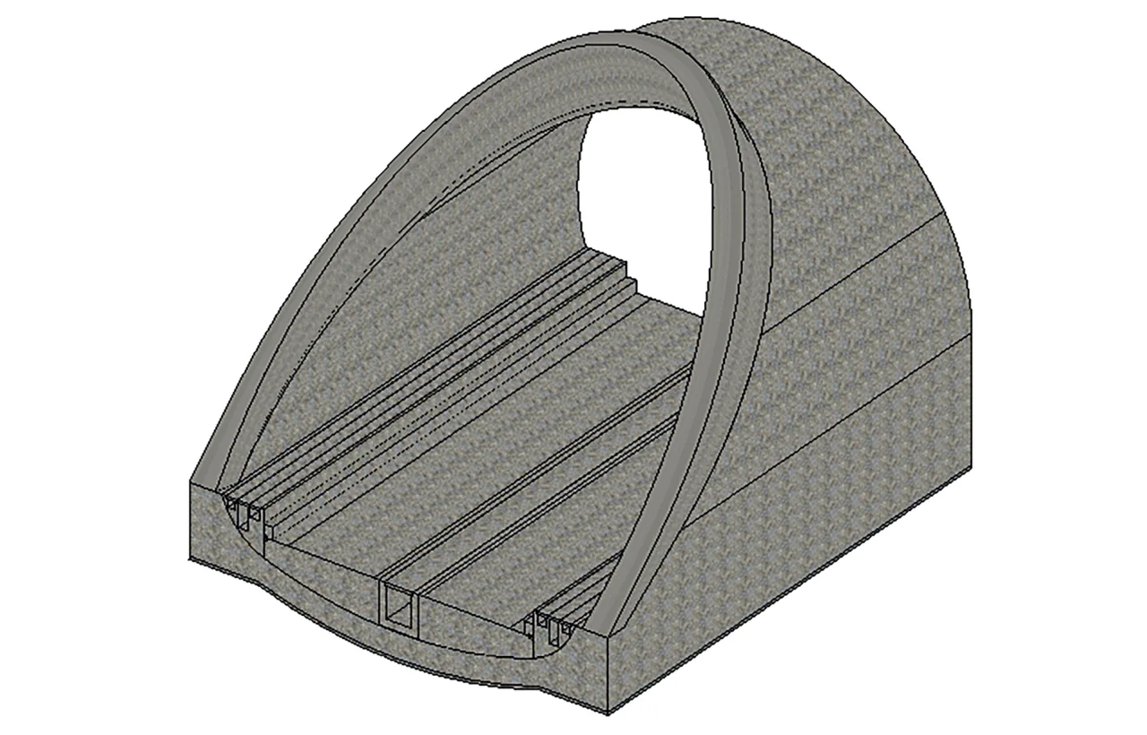
The tunnel body library includes families for covered tunnels, open tunnels, ancillary chambers, and auxiliary tunnels. Covered tunnel contours are categorized into common types such as single-center circle, three-center circle, and five-center circle. Key parameters for each include lining, side ditches, invert fill, and central ditch. The development methods for ancillary chambers and auxiliary tunnels mirror those of covered tunnels.
Covered Tunnel Body Contour Families
Interface
Tunnels connect seamlessly with bridges, roadbeds, and other specialized structures along their routes—covering drainage, cable trays, and more. The interface family library supports automatic generation of these connective structures during design, ensuring smooth transitions between tunnel portals and adjacent bridge, roadbed, and specialty models. Based on engineering requirements, databases for bridge and subgrade interfaces have been developed, covering waterproofing and drainage openings, as well as cable tray structures. Waterproofing and drainage at tunnel entrances include intercepting gutters and transition sections, while cable trays comprise trough bodies and cover plate transitions.
Special Components
Given the varied general and special structural forms in tunnel engineering, a specialized component family library is gradually established and expanded based on site-specific designs. Currently, this library includes waste disposal sites, disaster prevention and rescue facilities, ventilation and drainage systems, special retaining walls, and support structures. Using ORD’s secondary development and algorithmic parameterization, these special structures are instantiated with parameters reflecting their unique features, such as retaining walls, steps, slopes, and waterproofing/drainage elements.
BIM Forward Design System
A tunnel BIM forward design system aligned with design workflows and habits has been developed based on ORD. Built on an online database, it enables collaboration within the tunnel profession and facilitates external data exchange. The system retains selected 2D design concepts while pioneering 3D design for tunnel bodies, portals, construction groups, and engineering calculations—delivering more precise, detailed, and intuitive BIM designs than traditional 2D methods. The system consists of six main modules: design management, general design, tunnel body design, portal design, special design, and design output.
Design Management
System administrators can assign initial design accounts and permissions. Upon login, designers receive access rights to specific lines and work sites, accurately mapped to system functions. The backend management tracks user actions and milestone events, enabling digital oversight of the design process. This module also supports initial input, import, and setup of line-level design information.
General Design
This module integrates parameterized contour design for main tunnels, auxiliary tunnels, and ancillary chambers. It allows for configuring longitudinal section parameters and supports full-process steel frame and grating design, laying the foundation for tunnel body and portal designs.
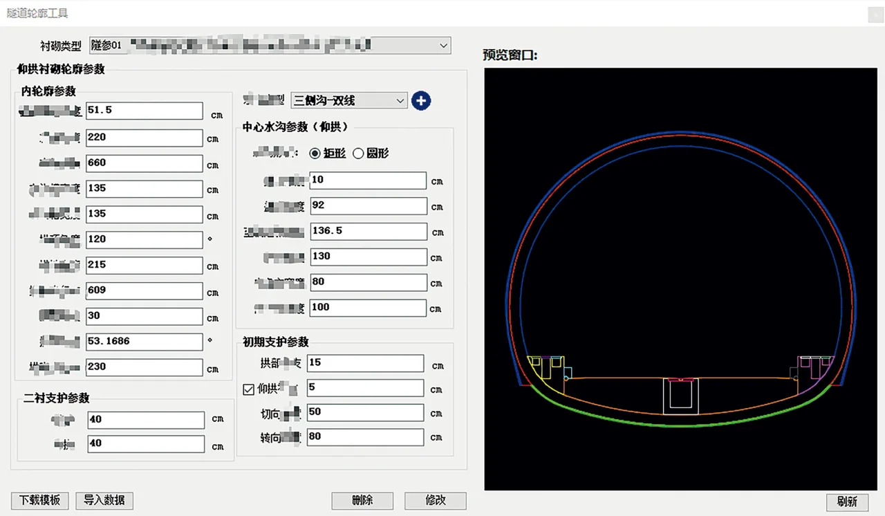
- Parameterized Contour Design: Combining numerical analysis and section fitting, key parameters are extracted and standardized tunnel sections stored. During input, parameter diagrams and real-time model previews assist designers. The program performs self-intersection and standardization checks to verify contours.
- General Parameter Configuration: Input tools cover lining parameters such as spacing, track slab height (ballasted and ballastless), drainage, and steps. Customization options for ballasted/ballastless forms and transition section heights enhance flexibility. Standard values for construction speed and depreciation are preset. Section components like electrical phase separation and insulation joints are specified to enable smooth longitudinal design.
- Steel Frame Design: A comprehensive steel/grating frame design tool supports node board definition, parameterized contour generation, model initialization, and node layout with visual interaction. Design data is stored in the database for reference drawings.
Tunnel Body Design
- Segmented Tunnel Lining Design: Key to tunnel body design, this module extends traditional 2D concepts via ORD secondary development. Through interactive operations, it enables rapid segmentation, insertion, movement, merging, and modification of longitudinal sections based on surrounding rock segmentation. It supports automatic updates of construction methods and support designs, semi-automatic anchor segment design via preset parameters, and quick widening of lining sections. By integrating geological data such as adverse geology and water inflow, special sections can be designed with one click. The module also offers one-click output of line spacing, geological data, and other tables for scalable map adjustments.
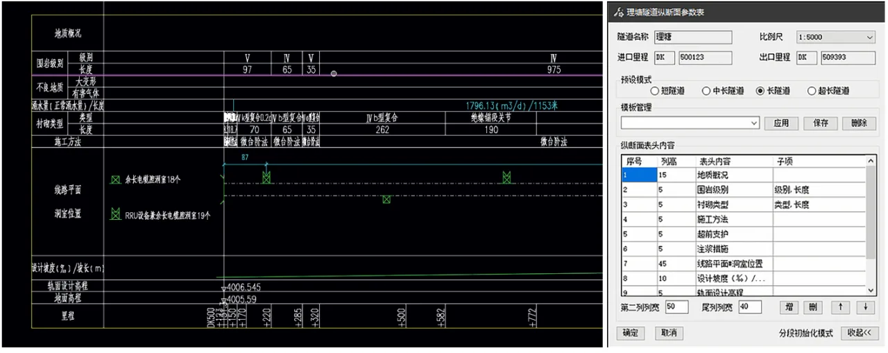
Tunnel longitudinal section design
- Ancillary Chamber Design: After segmenting the tunnel lining, auxiliary chambers can be batch-arranged by setting spacing and chamber types. The program automatically avoids construction joints and lining interfaces, optimizes chamber layouts, and supports one-click generation of tunnel plan drawings and tables.
Portal Design
Traditional 2D design often infers portal mileage from adjacent survey sections due to geological data limitations. BIM portal design optimizes this by applying 3D modeling to interception gutters, retaining walls, slopes, and more, significantly improving accuracy and design rationality while maximizing data sharing benefits.
- Mileage Determination: Supports cross-sectional views at any mileage with dynamic adjustment, helping designers quickly define key points like openings and light-dark boundaries, shifting from approximate to refined design.
- Interception Gutter Design: Designers can draw planar splines manually or generate gutters automatically from edge slope boundaries. Real-time display of water pit numbers and positions, along with quick gutter section selection from a library, enhances scientific design.
- Retaining Wall Design: Supports preset heights from 4 to 10 meters with local parameter modification. Selecting wall top points allows quick design completion, and parameters can be edited post-design for rapid adjustments.
- Slope Design with Sloping Edges: Visualization tools enable slope section design, with parameters stored in a backend database for team reference. Slopes can be generated quickly by selecting terrain and endpoints. A slope connection tool helps create continuous slope models. Completed designs facilitate excavation volume measurement when combined with 3D terrain models.
Special Design
Long, complex tunnels require special designs including construction groups, slag yards, ventilation, and disaster prevention and rescue. Rapid design capabilities for construction groups and slag yards are largely established, while ventilation and disaster prevention features remain under development.
- Construction Group Design: Utilizing preset construction speeds and reduction data, the system suggests construction plans based on rock conditions and lining segmentation. Users can refine designs via editing tools. Features include quick intersection surface solving, automatic construction line drawing, flat guide construction drawings, rapid auxiliary tunnel addition, and one-click construction drawing generation to aid accurate and efficient design.
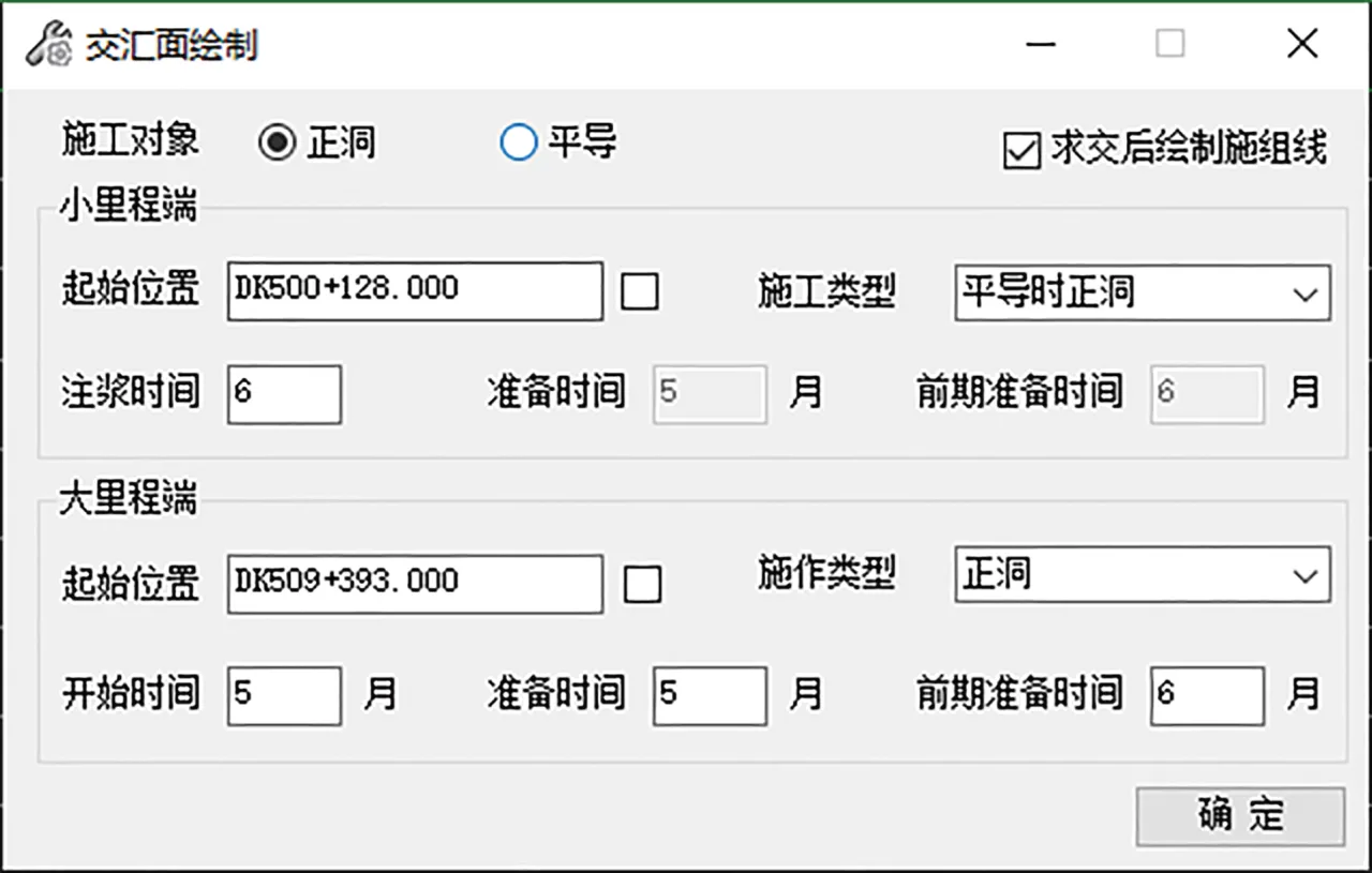
Solving the intersection surface of construction
- Slag Yard Design: Users can draft initial slag yard plans, define stacking areas with wireframes, and design retaining walls considering terrain. A 3D model combining terrain, support structures, and yard elements is generated to calculate volumes for design validation. One-click profile maps and quantity reports can be produced.
Design Output
This module focuses on 2D drawing generation, engineering quantity output, and 3D model creation to support design delivery to all construction stakeholders.
- 2D Drawings: Automatically generate parameterized design frames by selecting drawing dimensions and review levels. The system auto-fills content based on login data. Longitudinal section drawings dynamically update according to design results, ensuring compliance with drawing standards.
- Engineering Quantity Calculation: Supports importing and calculating in Excel while associating tunnel data from the database. Results can be output as Excel, CAD, or ORD charts. Future plans include encapsulating quantity calculation methods within the system for flexible and independent operation without relying on external files.
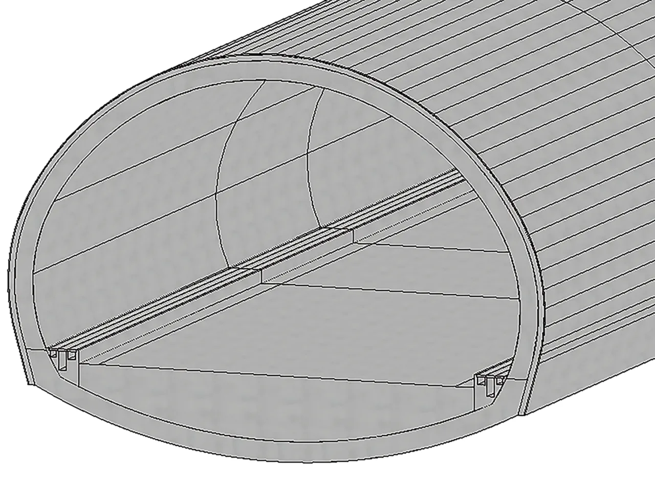
- 3D Modeling: Upon completing tunnel body and portal designs, a batch generation tool rapidly creates models for main tunnels, ancillary chambers, and auxiliary tunnels. The system reads longitudinal section data, verifies segment lengths, and assists in model construction, automatically performing Boolean operations between intersecting elements (e.g., auxiliary chambers and main tunnels). It supports one-click generation of detailed models based on standard lining sections, including advanced supports, initial supports (steel frames, shotcrete, steel mesh), and secondary lining (formwork concrete, steel reinforcement) with LOD400 accuracy.
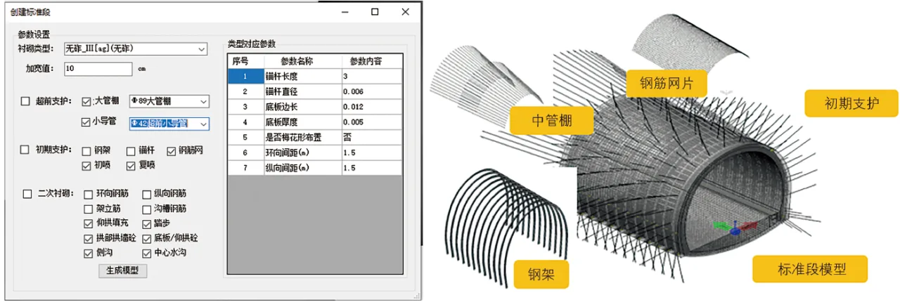
Detailed model of standard lining section
Through its application and refinement on projects such as the Chengdu Chongqing Central Line, Xikun Line, and challenging mountainous railways over the past two years, the tunnel BIM forward design standards, template library, and design assistance systems have matured and stabilized. The widespread adoption of tunnel BIM forward design clearly demonstrates advantages over traditional 2D methods.
Currently, 2D design remains the primary approach for high-speed railway tunnel engineering in China. However, as BIM forward design technology advances, BIM is expected to gradually replace 2D design. Future development will focus on three main areas:
- Standard System Improvement: Establishing a professional, scientific standard system for high-speed railways to enable standardized modeling, uniform interfaces, and clear deliverables, laying the foundation for BIM forward design across the railway professions.
- Expansion of Standard Family Library: As pilot projects deepen, the family library will become richer and more closely aligned with standards, forming a practical and standardized resource. Combined with family library management system development, BIM design for high-speed railway tunnels will become more efficient and precise.
- Iterative Updates of BIM Forward Design System: Given the lengthy development cycle, extensive pilot applications will validate the system. Each function will undergo iterative improvements to ensure design accuracy and comprehensive data delivery.
Content source:
Member Unit of Railway BIM Alliance – China Railway Eryuan Engineering Group Co., Ltd
Li Junsong, Wang Ming, Cao Li – Research and Application of BIM Forward Design in High-Speed Railway Tunnel Engineering, Railway Technology Innovation


Must log in before commenting!
Sign Up