The BIM model of the Wulongjiang Grand Bridge is developed based on construction design blueprints. During the modeling process, the bridge axis for the target area is established according to the bridge’s structural characteristics. Next, a reference axis network is created based on the bridge span layout and segment division to ensure precise spatial positioning. The complete bridge model includes main structures such as steel box girders, concrete box girders, steel-concrete composite box girders, bridge piers, pier foundations, high and low towers, and diagonal cables. Additionally, it incorporates ancillary elements like railings, ballast walls, tower ladders, and tower platforms.
The overall structure is primarily modeled using Revit, with some components achieving an accuracy level of LOD350. This includes modeling steel reinforcement and prestressed pipelines. Specific materials are assigned to each component, and with the Twinmotion plugin, the models are merged and exported in FBX format according to material types. These files are then imported into the BIM film virtual construction system, preserving the hierarchical structure so each unit can be individually selected and animated. Figure 4.2 illustrates the overall BIM model rendering of the Wulongjiang Grand Bridge (after Revit modeling, files are exported in DAE format, imported into Lumion software for rendering; the yellow section highlights the steel box girder).
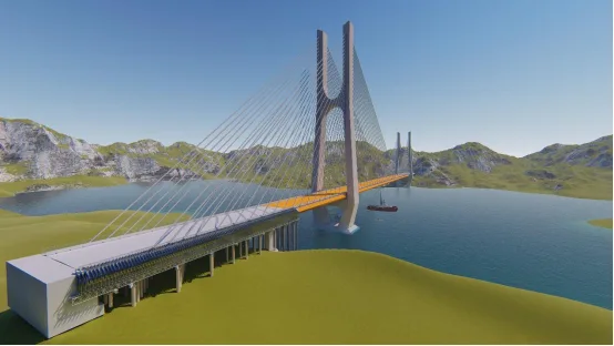
Figure 4.2 Overall BIM Model Rendering of Wulongjiang Grand Bridge
Bridge Model Creation
The Wulongjiang Grand Bridge is modeled at LOD350 level, covering key elements such as bridge piers, high and low tower columns, steel anchor beams within tower columns, concrete box beam sections on both sides, steel beam sections, prestressed ducts, locking pipes, railings, and ballast walls. The model contains detailed geometric dimensions and material types for major components, as well as internal steel reinforcement and prestressed steel bars embedded within the concrete.
The number of models is summarized in Table 4.1, while Figure 4.3 presents a schematic rendering of the bridge deck.
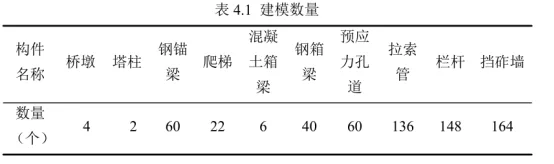
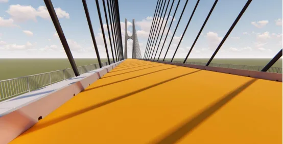
Figure 4.3 Schematic Rendering of Wulongjiang Bridge Deck Model
1. Parametric Modeling of Inclined Cables
Parametric modeling differs from traditional solid modeling by enabling rapid creation through parameter adjustments. By changing model variables, new models can be generated efficiently. This approach is applied to the bridge stay cables, which are numerous and located at complex points. Traditional modeling methods are time-consuming and less accurate. Using adaptive models of the stay cables along with the coordinates of their start and end points allows quick and precise placement of the cable models, as shown in Figure 4.4.
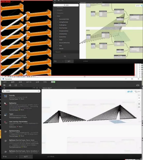
Figure 4.4 Parametric Model of Bridge Stay Cables
2. Principal Modeling
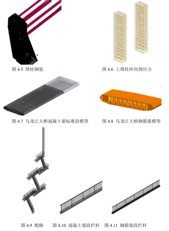
Based on construction drawings, the bridge is modeled in detail. Components with steel reinforcement, such as high and low towers (Figures 4.5 and 4.6) and concrete box girders (Figure 4.7), are created using Revit’s steel bar functionality, where steel bar sizes and models are defined and materials assigned. For prestressed steel bars in concrete box girders and tower column crossbeams, which have variable cross-sections, custom steel bar drawings are used to model complex prestressing. This allows accurate calculation of quantities, supporting material demand planning at the construction site.
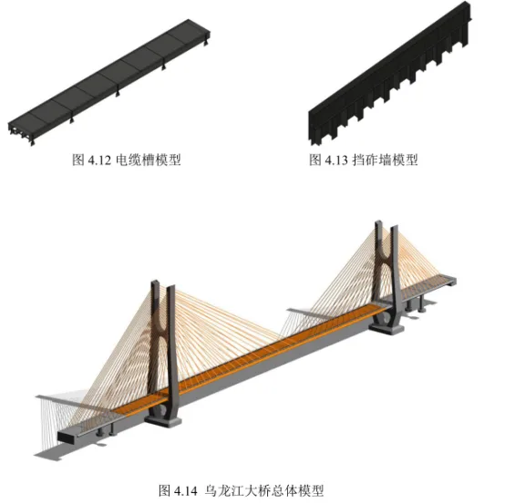
Prefabricated components such as steel box girders (Figure 4.8), tower ladders (Figure 4.9), railings (Figures 4.10 and 4.11), cable troughs (Figure 4.12), and ballast walls (Figure 4.13) are also modeled and verified against onsite requirements. After modeling individual families, they are combined within the project to complete the full bridge BIM model, as shown in Figure 4.14.
Field Layout Model Creation
Construction sites typically house a large quantity of materials and equipment. For bridge construction sites with limited space, efficient and orderly storage is a key management objective. This study utilizes BIM to simulate on-site layouts, optimize material stacking locations, and improve storage efficiency, making it suitable for constrained construction sites.
BIM enables dynamic balancing of material supply and demand by simulating the placement and installation locations of various infrastructure elements. This ensures rational machinery use and prevents collisions. Identifying such issues through traditional two-dimensional drawings, like the one shown in Figure 4.15, is challenging. Using the BIM model, the real spatial layout of the high tower column construction site is simulated. Large temporary facility locations are compared and selected based on actual site conditions. Due to a collision detected with the cage ladder in the original setup, its position was adjusted, leading to the optimized site layout shown in Figure 4.16.
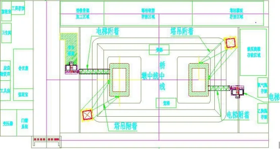
Figure 4.15 Construction Site Layout Plan
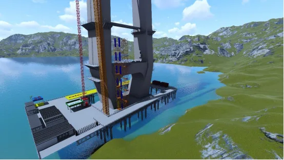
Figure 4.16 Optimized Field Layout Model
Quantity Surveying
Currently, construction technicians mainly use AutoCAD for 3D modeling, which excels for 2D plans but faces challenges with complex 3D railway bridge structures and component relationships. Modifications in one area can lead to extensive data changes, which must be manually adjusted in CAD, increasing the risk of oversight.
BIM technology interconnects all information, so changes in one part automatically update the entire model. This enables effective control over material storage, quick understanding of material inflow, usage, and inventory, rational allocation of labor and machinery, improved supplier efficiency, and better decision-making, ultimately achieving refined material management.
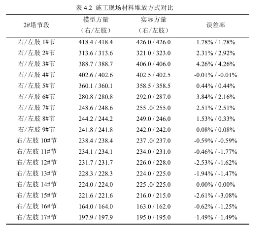
For this project, BIM models were used to calculate quantities for tower column concrete, steel reinforcement, prestressing, steel anchor beams, box beams, and other engineering components. Taking the concrete volume for the second tower section of the Wulongjiang Grand Bridge as an example, the BIM-calculated quantity was compared to actual construction data.
The concrete volume for the high and low towers was statistically analyzed using BIM software. Early in construction, pouring sections changed multiple times, necessitating repeated quantity recalculations. Traditional CAD methods are inefficient and struggle with irregular structures, especially when deducting cavity volumes manually.
With Revit modeling, sectional cuts can be quickly made for quantity analysis. Table 4.2 shows the maximum error between BIM estimates and actual concrete volume is just 4.26%, with a minimum error of 0.00%. This accuracy allows for precise forecasting of concrete needs, providing accurate task quantities for concrete plants and transporters—helping to avoid shortages or waste of concrete, machinery, and labor. Consequently, pouring tower column segments is completed efficiently and accurately.
Collision Detection
Traditional construction often encounters issues like steel reinforcement collisions, incorrect sizing, and delayed problem identification, leading to work stoppages, design changes, and safety risks. CAD drawings alone make it difficult to assess three-dimensional spatial relationships, making collision issues inevitable.
Before construction begins, collision detection is essential to ensure smooth progress and prevent material waste. Key collision checks include:
- Collision between the prestressed pipeline under the tower column crossbeam and the main reinforcement (Figure 4.17)
- Collision between the concrete prestressed pipeline and tooth blocks (Figure 4.18)
- Collision between the prestressed pipeline and inclined cables
Once the model is complete, collision detection helps identify conflicts for optimization and modification, significantly reducing cutting errors. This approach ensures safe, reasonable solutions and appropriate material use, avoiding rework and accelerating construction.
During the final construction technology review, BIM enables rehearsal of the construction process, improving worker efficiency, enhancing site safety, and elevating project quality.
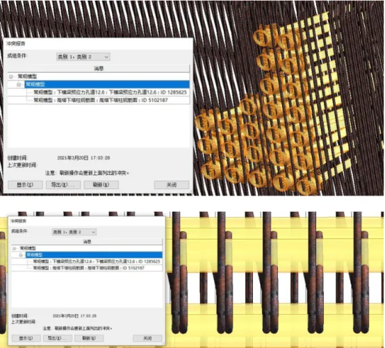
Figure 4.17 Collision between Prestressed Pipeline and Steel Reinforcement under Tower Column Crossbeam
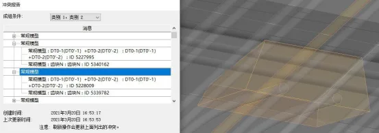
Figure 4.18 Collision between Concrete Prestressed Pipeline and Tooth Block
A collision was detected between the prestressed pipeline and the inclined cable on the high tower crossbeam, as shown in Figure 4.19. Using BIM visualization, the following issues were identified and resolved:
The collision point between the prestressed pipeline on the high tower crossbeam and the inclined cable conduit was adjusted. Flat and vertical bends were applied to the end of the conflicting prestressed pipeline, modifying its parameters to eliminate the collision. This adjustment is illustrated in Figures 4.20 to 4.22.
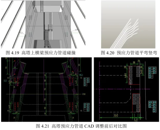
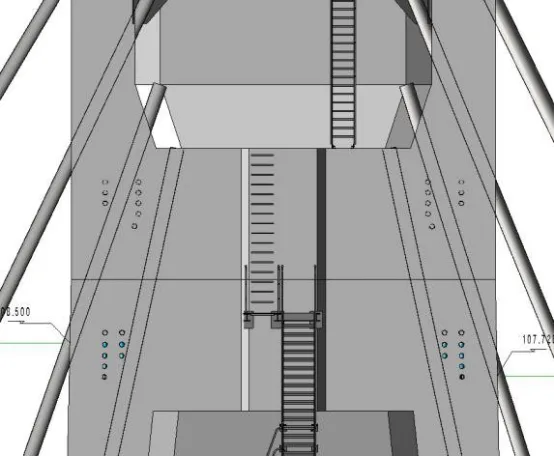
Figure 4.22 Adjusted BIM Model of the High Tower Prestressed Pipeline
Spatial Inspection
BIM models not only detect collisions between components but also perform detailed spatial checks within components. They simulate site layouts and pre-verify installation and maintenance spaces to ensure adequacy.
The concrete box girder contains extensive steel reinforcement, prestressing, and tooth blocks, resulting in a complex spatial structure. Two-dimensional drawings are insufficient to identify potential issues or determine the location for beam top openings.
Using BIM models to simulate real space allows detection of spatial relationships within the box girder, determining appropriate opening positions and meeting on-site construction requirements. This is demonstrated in Figures 4.23 to 4.25. Through spatial inspection, material parameters such as embedded parts and steel bars can be defined in advance, enabling timely material adjustments. This predictive capability improves material utilization and structural safety.
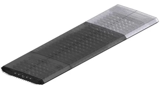
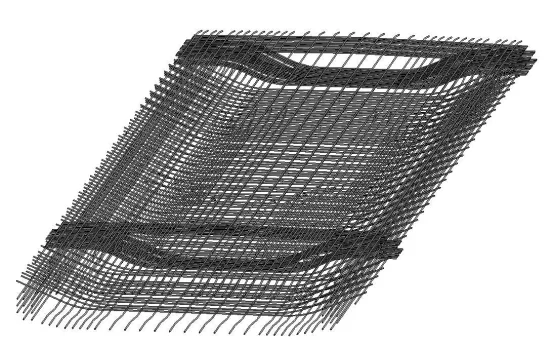
Figure 4.23 Concrete Box Beam Model
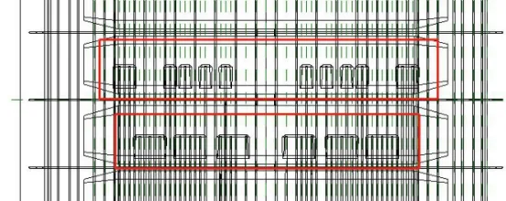
Figure 4.24 Relationship between Concrete Box Beam Tooth Blocks and Reinforcement
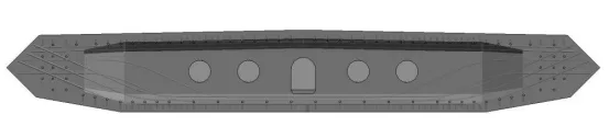
Figure 4.25 Simulation of Reinforcement Position in Concrete Box Beam
Xu Mengni (Hubei University of Technology)
For learning and communication purposes only. Copyright belongs to the original author. If there is any infringement, please contact us for removal.


Must log in before commenting!
Sign Up