This article is from the official TopsBIM account.
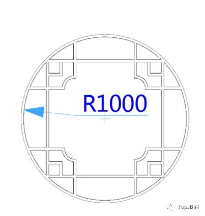
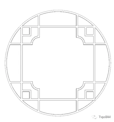
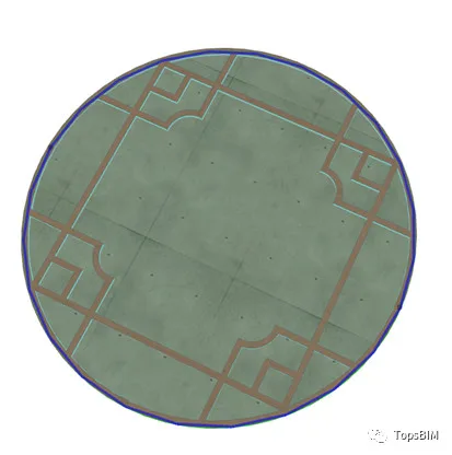
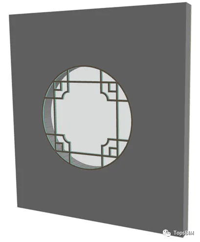
In real-world project design, the door and window styles available in the ARCHICAD library often fall short of our requirements. How can we create doors and windows with irregular shapes when needed? This tutorial will guide you through the process of creating an irregular window, using the example shown in the image below.
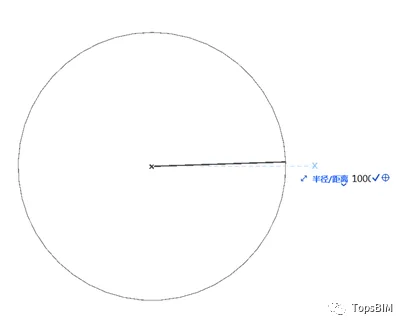
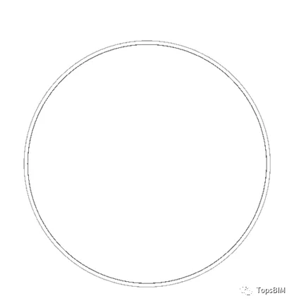
1. First, select the “Arc/Circle Tool” from the toolbar and draw a circle with a radius of 1000mm.
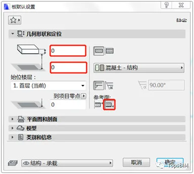
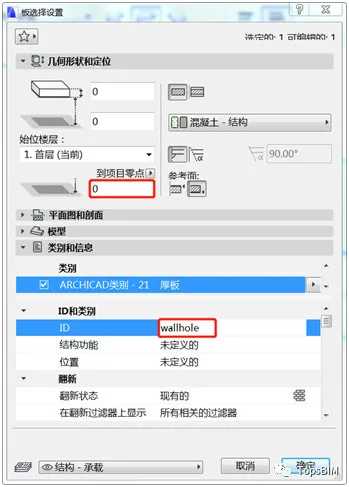
2. Open the board tool’s default settings dialog. Set the board thickness to 0mm, the offset from the base floor to 0mm, and the reference surface to the bottom.
3. With the board tool active, hold down the spacebar and click on the circle you just drew to create a board with zero thickness.
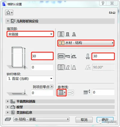
4. Select the wall tool, set its top to unlinked, height and thickness to 30mm, material to wood – structure, and reference surface to the outer side. Hold down the spacebar and click around the board to generate a wall.
5. Continue using the wall tool to design the internal structure of the window as illustrated below.
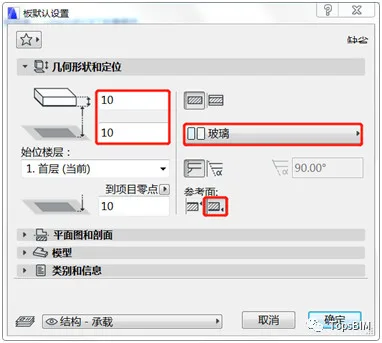
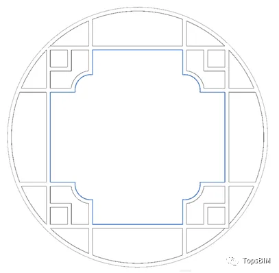
6. Now, let’s create the window glass. Open the panel default settings dialog, set the reference surface to bottom, offset from base floor to 10mm, thickness to 10mm, and material to glass. Use the magic wand tool to fill the blank areas enclosed by the walls with panels.
7. Select the original board you created, ensure the minimum height is set to 0, and rename its ID to ‘wallhole’.
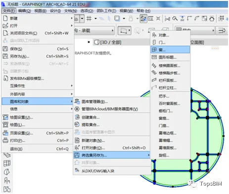
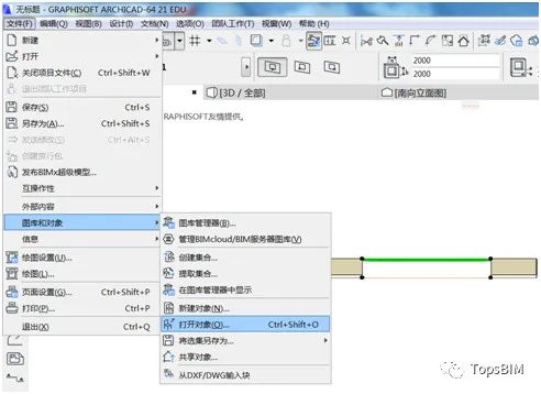
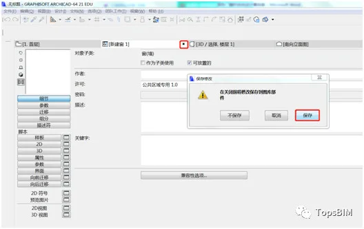
8. Select all the components you’ve created, then go to File > Gallery and Objects > Save Selection as > Window to save your new window object.
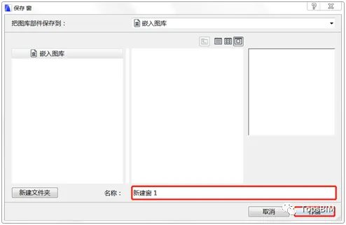
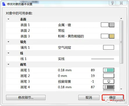
9. In the popup save dialog, enter a name for your window, click “Save”, adjust the basic settings as needed, and then click “OK”.
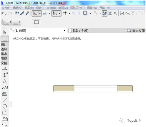
Create a wall and insert your newly created window, as shown below:
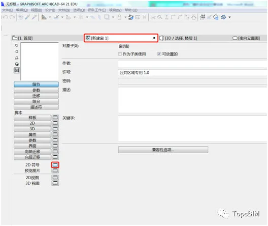
10. Next, let’s adjust the 2D display of the new window. Select the window, then go to File > Gallery and Objects > Open Object.
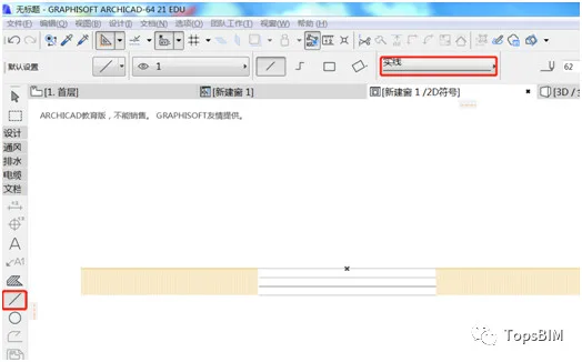
11. In the pop-up window, click the icon shown below to open the 2D symbol panel.
12. Use the line tool to draw a straight line segment on the 2D symbol panel as shown. After finishing, close the New Window interface and save your changes.
Back in the floor plan, the final result looks like this:
Note: If there is any code in the 2D script during step 11, please delete it. Otherwise, the script will override the 2D symbol display in the floor plan.


Must log in before commenting!
Sign Up