This article is from the WeChat official account: PCers.
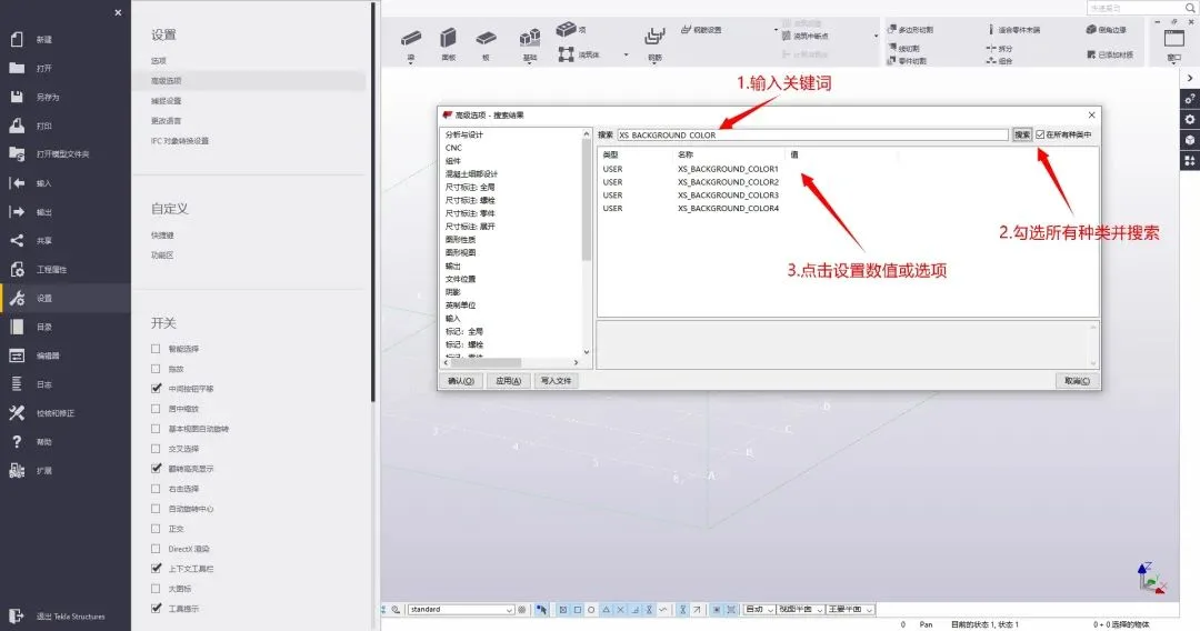
Tekla users can access advanced settings by navigating to Settings > Advanced Options in Tekla’s file menu. This opens a dialog box where various advanced options can be configured.
Changing the Drawing Interface Color
The XS_SLACK-DRAWING_Sackground setting controls the interface color of the drawing environment.
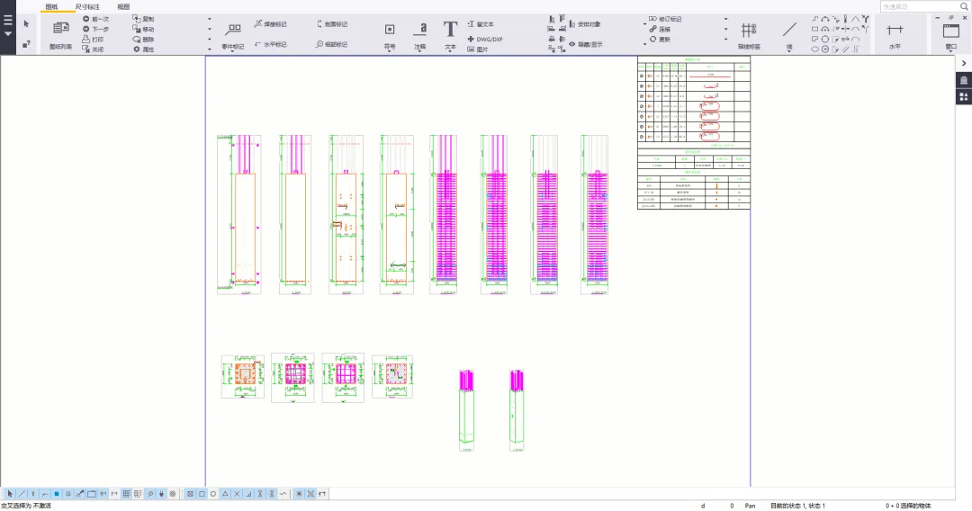
Setting the value to False results in a white drawing interface:
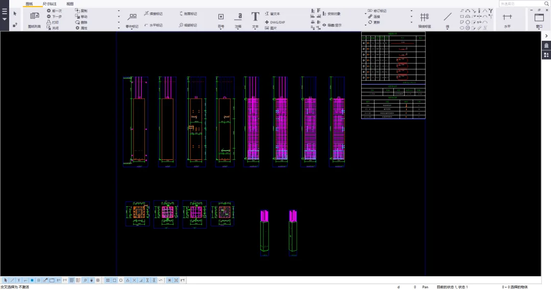
Setting the value to True switches the interface to black:
Setting Background Colors for Model View Interface
The background colors of the model view interface are controlled by four settings:
XS_SACKGIND_COMPLOR1– Top-left cornerXS_SACKROUND-COLOR2– Top-right cornerXS_SACKGIND_OLOR3– Bottom-left cornerXS_SACKROUND-COLOR4– Bottom-right corner
Use RGB values where 0 0 0 represents black and 1 1 1 represents white.
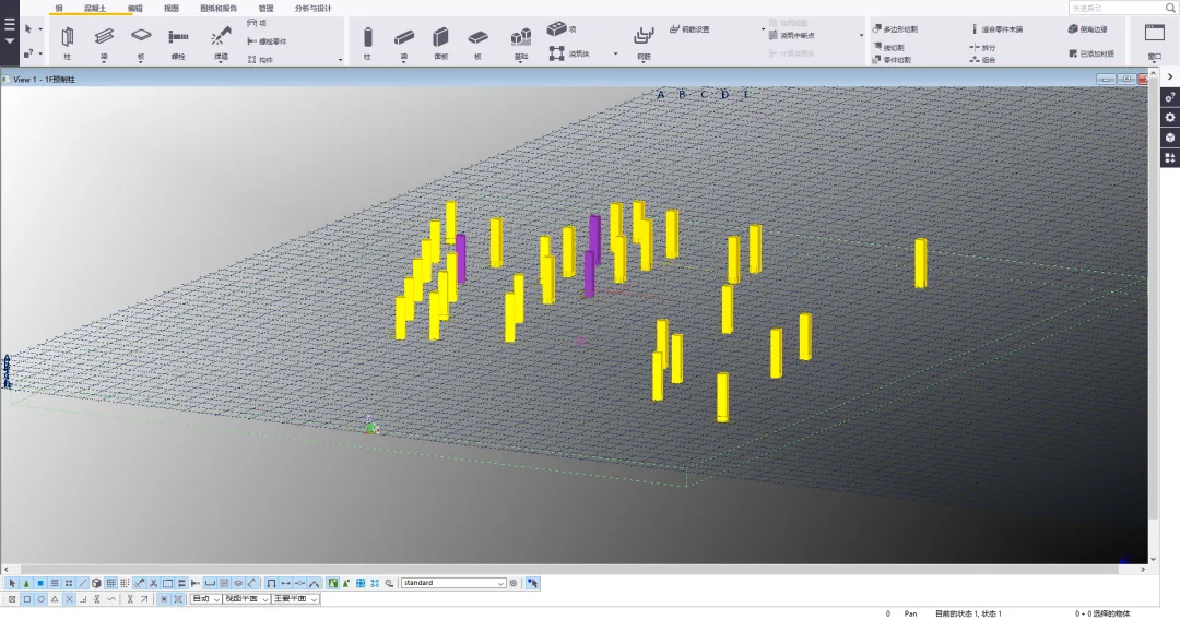
Example values in sequence: 1 1 1, 0.5 0.5 0.5, 0.8 0.8 0.8, 0 0 0 0.
Another example sequence of values: 0 0 0, 0 0 0 0, 0 0 0 0, 0 0 0 0.
Text Settings in Reinforcement Group Dimension Annotations
The XS-COMBINED_BOLTDIM_CARACTER option sets the characters used in the dimension labels of steel reinforcement groups.
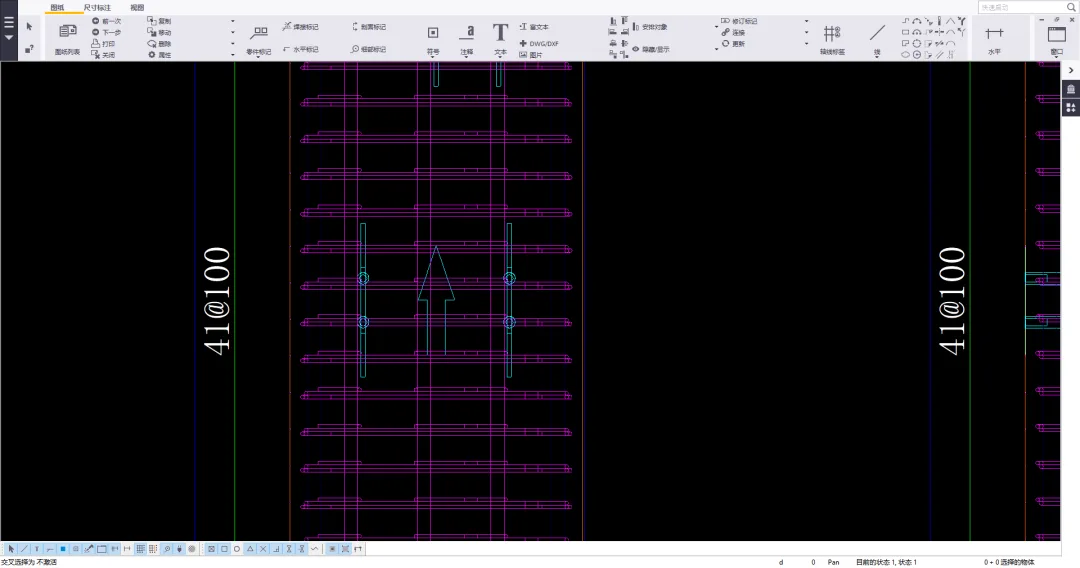
When set to @, the reinforcing steel character is displayed:
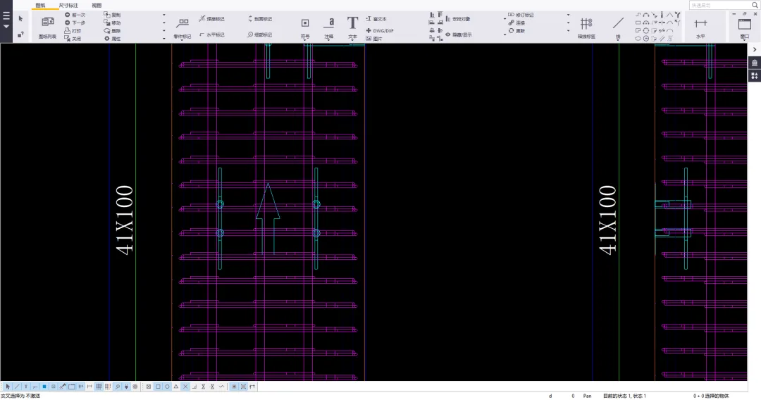
When set to X, the reinforcement character is displayed:
Cutting Surface Color Settings
Set the cutting surface color of parts using the XS-DRAW_CUT-FACE, WITH, and RED-COLOR options.
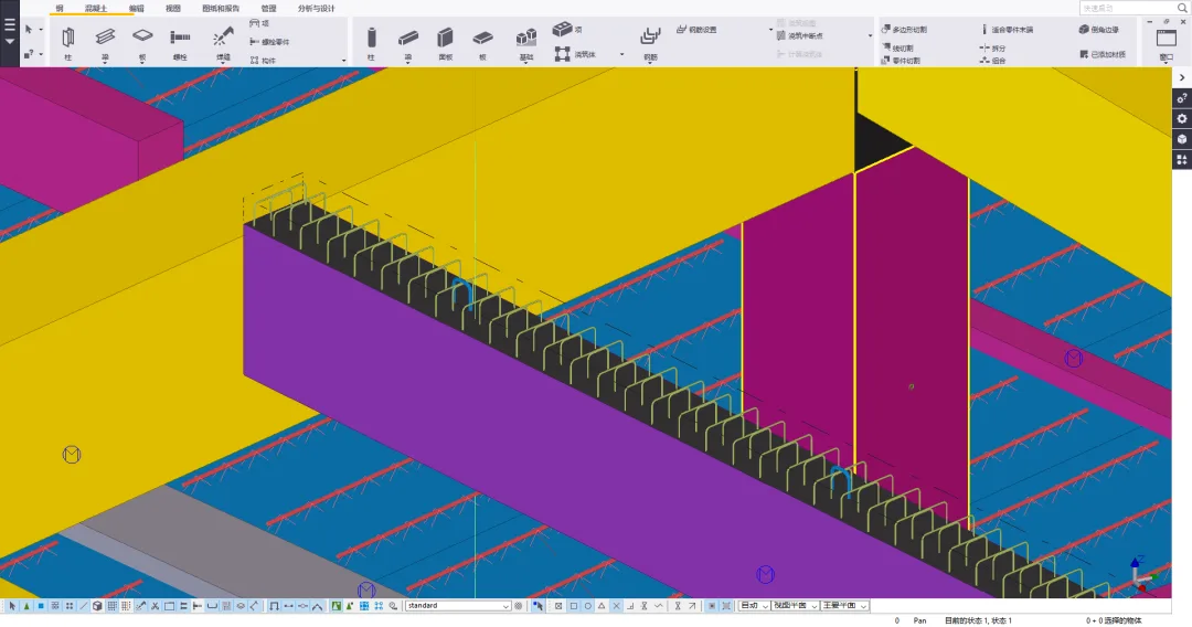
Setting the value to True makes the cutting surface black:
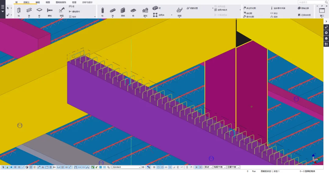
Setting the value to False matches the cutting surface to the part’s surface color.
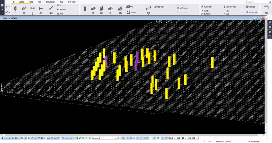
Axis Color Settings in Rendering Mode
The XS_GRID_COLOR option controls the color of axis lines.
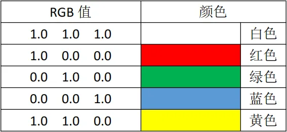
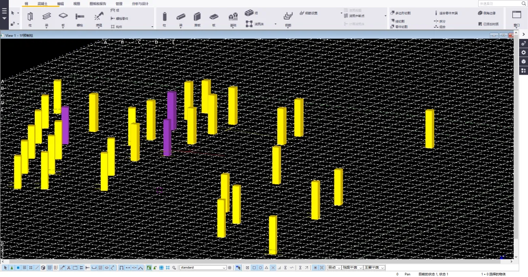
When set to 1.0, 1.0, 1.0, the axis lines appear white:
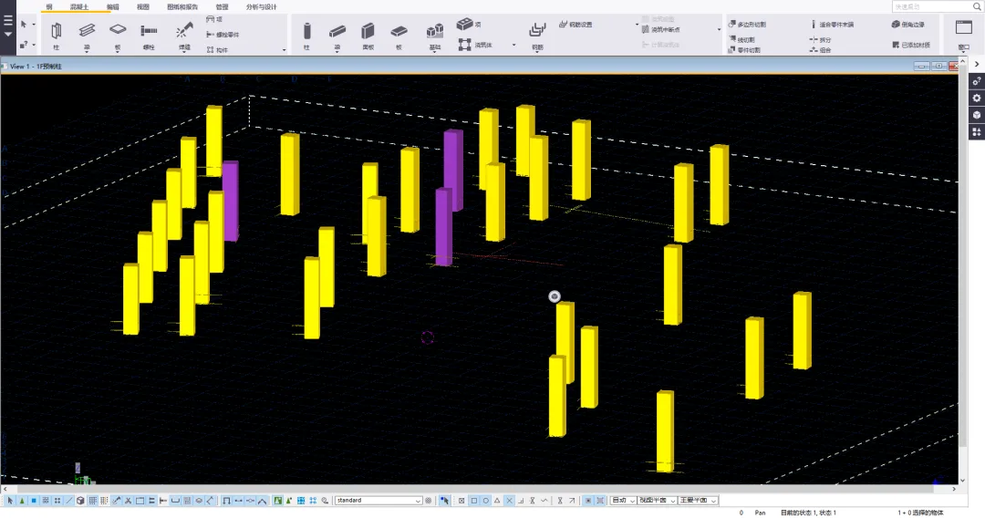
When set to 0.0 0.0 1.0, the axis lines are blue. Note that if the axis and background colors are similar, visibility can be poor.
The color of the work plane axis line can be set using the XS_GRID-COOR-FOR_SWORK-PLANE option.
Customizing Drawing Types and CAD Output File Names
- Component Drawing:
XS-DRAWING-PLOTFHIR NAMA_A - Part Drawing:
XS-DRAWING-PLOT_CILENAMA_W - Multi-piece Image:
XS-DRAWING-PLOTFHIR NAME-M - Overall Layout Drawing:
XS-DRAWING-PLOTFHIR NAME_G - Pouring Body Drawing:
XS-DRAWING-PLOTFHIR NAME_C
For example, to customize the pouring body drawing filename, change XS-DRAWING-PLOTFHIR NAME_C to %DRAWING_TITLE%.
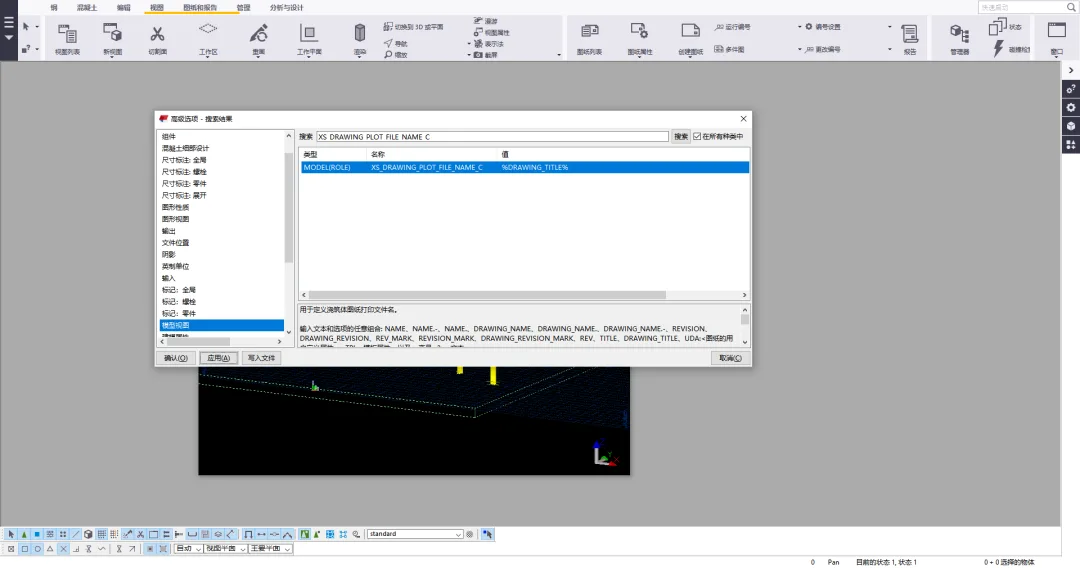
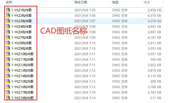
Example of the output CAD drawing filename:
Arrow Size Settings in Marked Leader Lines
XS-MARK_LEADER-LINE_SRROW_SEIGHT controls the arrow height.
XS-MARK_LEADER-LINE_SRROW_LENGTH controls the arrow length.
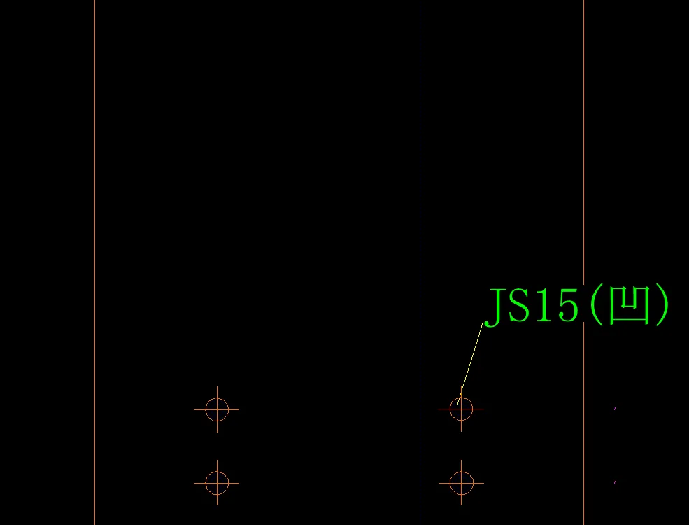
Example values: 1 (height), 1.5 (length).
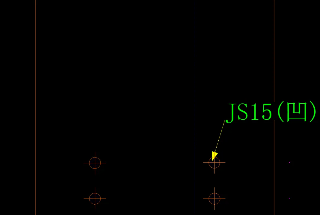
Another example: 20 (height), 30 (length).
Dimension Line Size Settings
XS_DIMENSION_EXTENSION_LINE_AWAY_FACTOR controls the length of the extension line away from the dimension line, as shown by the red line in the image below:
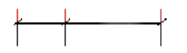
XS_DIMENSION_EXTENSION_LINE_TOWARD_FACTOR controls the length of the extension line toward the dimension line, indicated by the red line below:
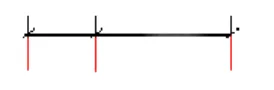
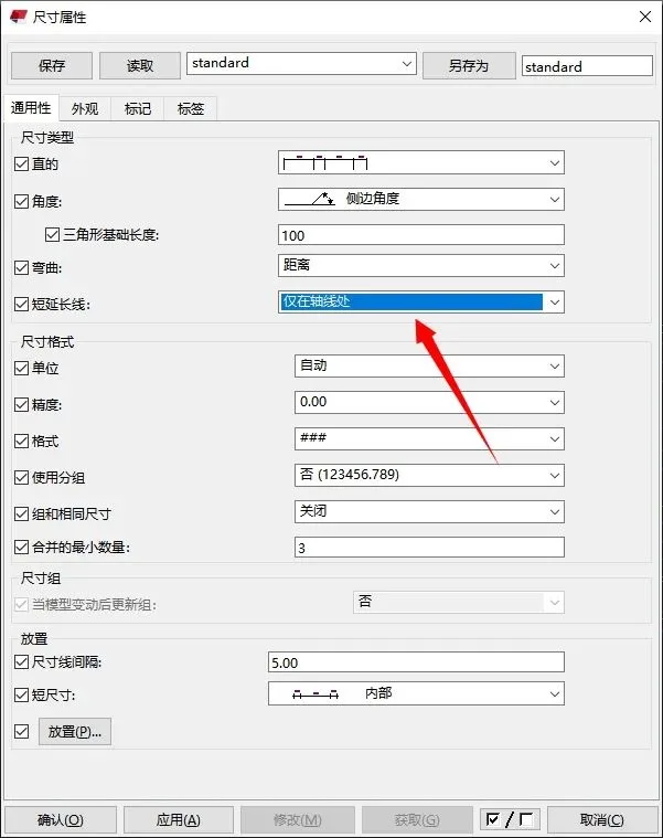
Note: These options only apply if the “Short Extension Line” option is enabled or when applied only to the axis line in the dimension properties dialog box.
Example values: 0.5 (away), 0.5 (toward).
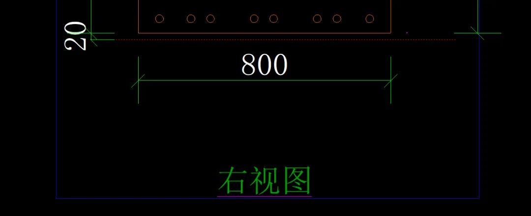
Another example: 1 (away), 1 (toward).
Saving Backup Copies of Multiple Versions
The setting XS-STORE.MMULTIPLE_BAK_FileS controls whether multiple backup copies are saved.
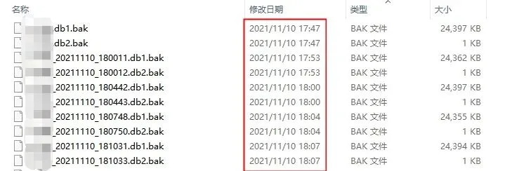
Setting this value to True enables saving backup copies of multiple versions.
Allowing View Windows to Move Freely on the Windows Desktop
The XS_SDIVIEWPARENT option controls whether view windows can be freely moved on the Windows desktop.
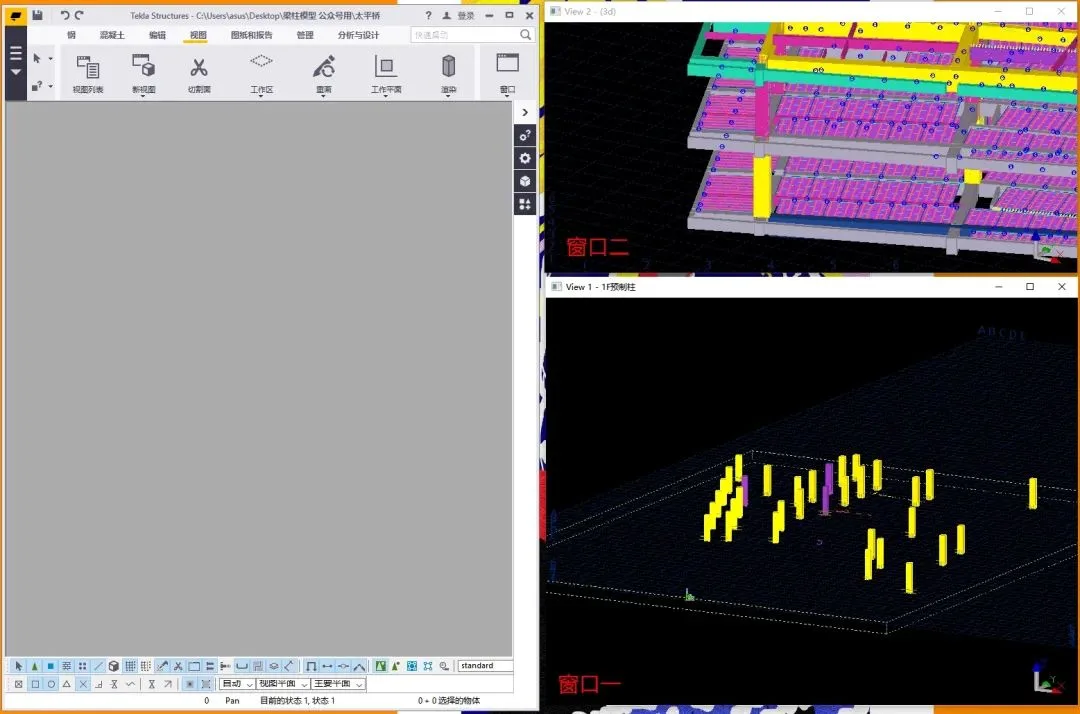
When set to False, this setting allows view windows to move freely across the Windows desktop.


Must log in before commenting!
Sign Up