Source: Shaanxi Xiaoge Technology Co., Ltd
There’s a common misconception that steel bars cannot be created in Revit and that the software lacks steel bar functionality. This is not true.
In Revit, you can not only create steel bars but also calculate their shape, quantity, length, weight, and more. Let’s start by learning how to create steel bars.
First, ensure you are working in a structural project, and create steel bars within a section view — both conditions are essential.
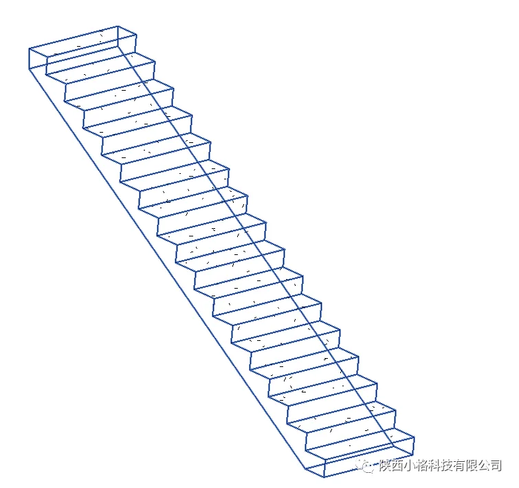
Let’s use stairs as an example to illustrate how to draw steel bars.
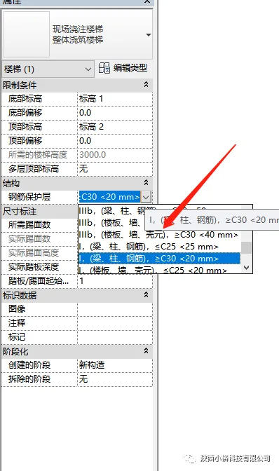
Select the staircase, then in the properties panel, adjust the thickness of the steel reinforcement cover layer as needed.
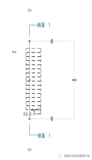
Since steel bars can only be created in section mode, switch to the plan view, then create a section box to enter the section view.
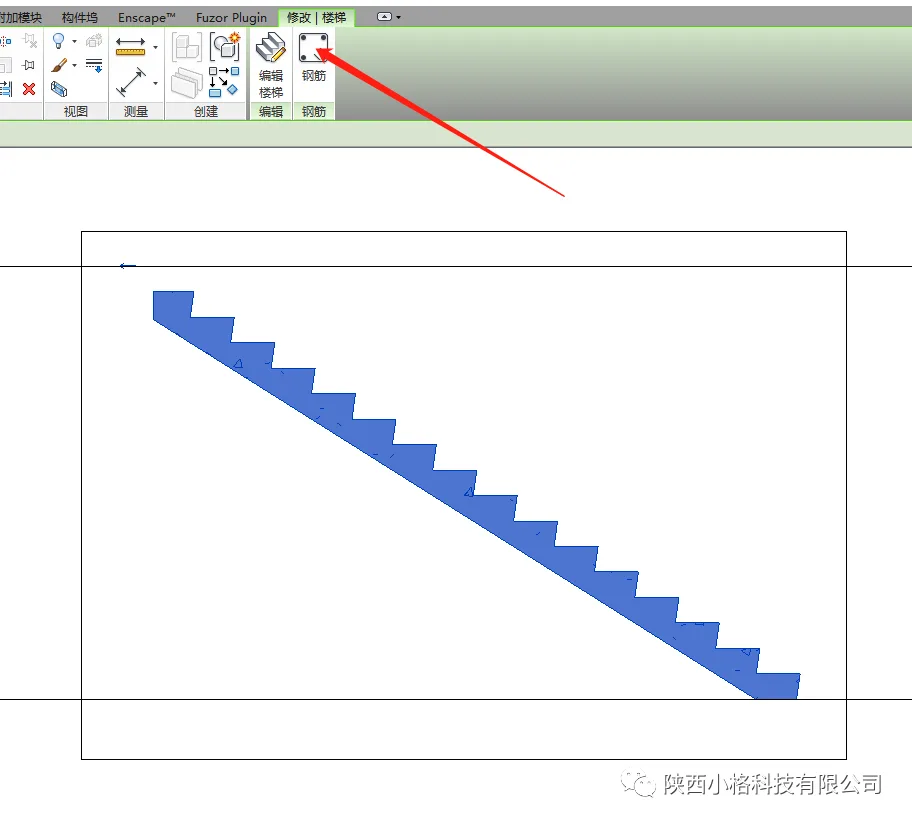
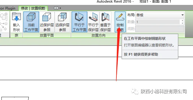
In the section view, select the stairs, then use the steel bars tool in the toolbar above to start drawing.
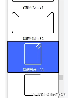
Within the steel bar command box, select the steel bar type in the properties bar and choose the layout shape from the shape browser.
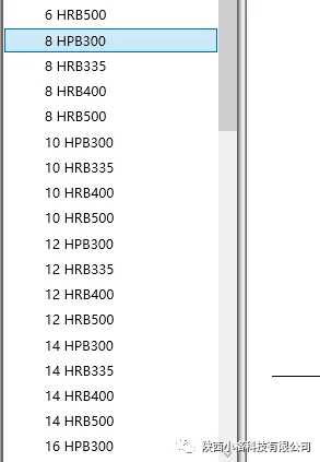
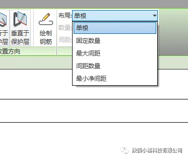
You can select your desired steel bar model and layout shape, arranging them manually or using automatic spacing settings. Feel free to experiment with these options.
How do you handle steel bars with special shapes? You can use the steel bar drawing command to create any custom shape you need.
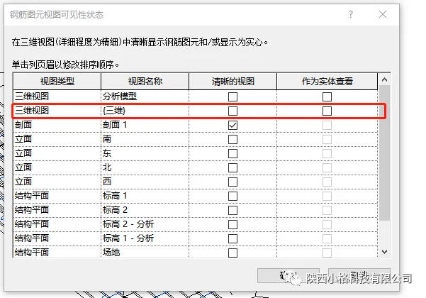
To make the steel reinforcement visible as a solid model in the 3D view, select the steel bars, then in the properties panel under graphics, choose the editing options and check the “Show as Solid” box.
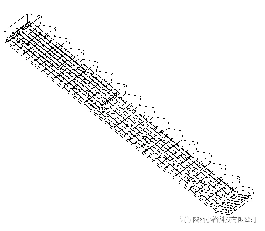
And with that, the creation of steel bars is complete.


Must log in before commenting!
Sign Up