Engineering Background
The Changsha Huanghua Comprehensive Bonded Zone is situated near Huanghua Airport in Changsha, Hunan Province. The North Checkpoint serves as its “gateway” project, featuring an integrated design resembling an airplane.
The upper structure primarily uses a single-layer mesh shell with a hyperbolic arch shape. The connecting nodes consist of intersecting welded joints. The upper mesh shell’s “two wings” are supported by box-shaped pier columns on both sides, each having a cross-section of 400 × 16 mm. At the center of the mesh shell is a sightseeing steel platform, with a rotating steel staircase positioned below it.
The North Checkpoint stands approximately 14 meters tall. The main cross-sectional dimensions of the steel mesh shell are Φ 400 × 20 mm, Φ 273 × 16 mm, Φ 159 × 10 mm, and Φ 102 × 7 mm, all fabricated from Q345B steel.
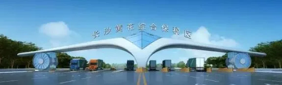
Rendering
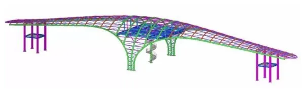
Structural 3D Diagram
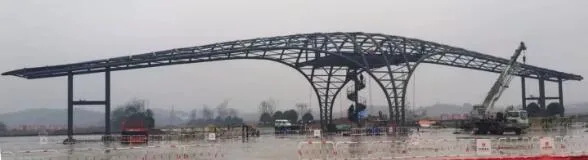
On-site Assembly Diagram
The North Checkpoint features a complex design, requiring the main structural construction to be completed within one month, imposing significant pressure on the project timeline. Its hyperbolic arch shell structure is rare in China, and some members require bending in two directions, making fabrication challenging. The mesh shell uses intersecting line welding nodes, demanding high precision during construction, which complicates on-site installation.
Various construction methods are available for shell structures, including high-altitude bulk assembly, strip or block installation, sliding, integral lifting, integral jacking, and folding/unfolding integral lifting. Considering site conditions, only the high-altitude bulk method or segmented lifting method are feasible for the North Checkpoint shell.
High-altitude Bulk Method: This approach provides a wide working surface, facilitates accurate adjustment of individual rods, and requires smaller lifting equipment. However, it needs a full support frame, results in many high-altitude butt welds that are difficult to control for deformation, and the construction period is hard to guarantee.
Block Lifting Method: This method reduces high-altitude work, allows easier control of welding deformation on the ground, and ensures the construction schedule. However, it requires high precision during assembly, a larger selection of lifting equipment, and presents difficulties in high-altitude positioning during segmented lifting.
Considering factors such as project duration, cost, and precision control, segmented lifting is deemed the most suitable method for the North Checkpoint. The construction sequence involves first lifting the box-shaped piers on both sides, followed by lifting the upper mesh shell in sections, and finally lifting the central sightseeing platform.
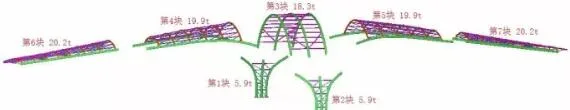
Grid Shell Block Layout and Supporting Tire Frames
The upper mesh shell is divided into seven blocks for hoisting due to the unique form of the North Checkpoint. After lifting the blocks, the missing rods between them are promptly installed.
Supporting Tire Frame Layout
Considering site conditions, a support system consisting of eight supporting tire frames and box-shaped pier columns is arranged at the junctions of each block, as shown in the diagram above. Calculations specify that the supporting frames are constructed from seamless steel pipes with a diameter of Ø 102 × 8 mm around four poles, connected by Ø 80 × 6 mm seamless steel pipe rods. The upper part uses 18# I-beams to support the platform. This support platform section also functions as an elevation adjustment section for the supporting tire frames.
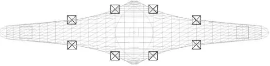
Supporting Tire Frame Plan Layout
On-site Construction Technology
Material Delivery
Component Inspection upon Arrival
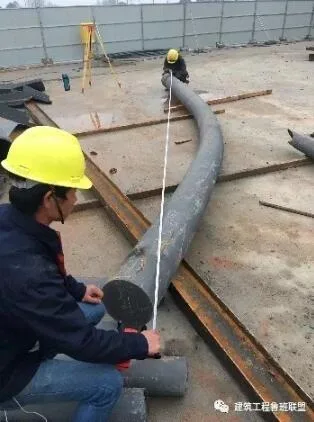
The North Checkpoint’s structure is distinctive, featuring a hyperbolic arch-shaped steel mesh shell with intersecting nodes. Manufacturing employs cold bending arc technology and intersecting line cutting, with component accuracy directly impacting installation quality. Dedicated personnel are stationed at the factory to oversee quality, ensuring all components are inspected and approved before shipment.
On-site inspection is conducted on a sample basis upon arrival, focusing on component dimensions, paint thickness, intersecting line cutting accuracy, and bending precision (height). Components are sorted and stacked by number on-site, with care taken to protect finished products.
Ground Assembly
Ground assembly is the most convenient and critical phase for quality control in shell structure construction. This project uses an in-situ assembly method, summarized as follows:
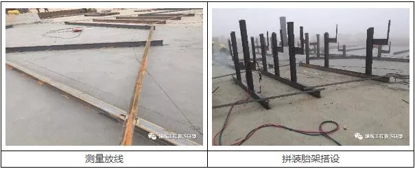
- Measurement and Layout: Using drawings, calculate the horizontal projected coordinates for each segmented mesh shell. Employ a total station to locate each node with an accuracy better than 1 mm, marking cross-shaped points on the ground. The outermost area is slightly extended to allow welding shrinkage. To avoid instrument errors, layouts are performed under consistent outdoor conditions, and all segmented mesh shells are laid out in a single session without repositioning the instrument.
- Assembly Tire Frame Installation: Assembly jigs made of 20A I-beams form inverted T-shaped supports erected above each segmented mesh shell, aligned per the total station coordinates. Support cow legs are welded atop the tire frames, reinforced with L50 × 5 angle steel to prevent tipping. Precise elevation control of the cow legs is critical to positioning members accurately. A thorough inspection of the entire tire frame assembly is conducted before proceeding.
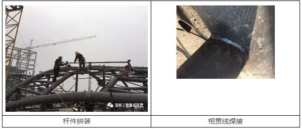
- Rod Assembly: Based on detailed drawings and assembly tire frame positions, members are assembled using a plumb bob for alignment. Primary members are installed first, followed by secondary ones, with node center deviations kept under 2 mm. After positioning primary members, they are temporarily fixed with horse boards to ensure stability during subsequent assembly. Secondary members are marked, adjusted for plane position and elevation, and then spot welded.
- Intersection Line Welding: After assembly, all dimensions and groove conditions are verified before welding. The welding sequence prioritizes members prone to greater deformation, starting from the middle towards the sides, smaller weld seams before larger, higher stress members before lower, tension rods before compression rods, and larger diameter members before smaller ones. Butt welds of main components use two-person symmetrical welding.
- Weld Seam Inspection: After 24 hours post-welding, ultrasonic testing is performed to assess weld quality internally. A weld gauge checks the weld foot dimensions at the toe and root of intersecting seams. Only welds passing inspection are approved before formal hoisting.
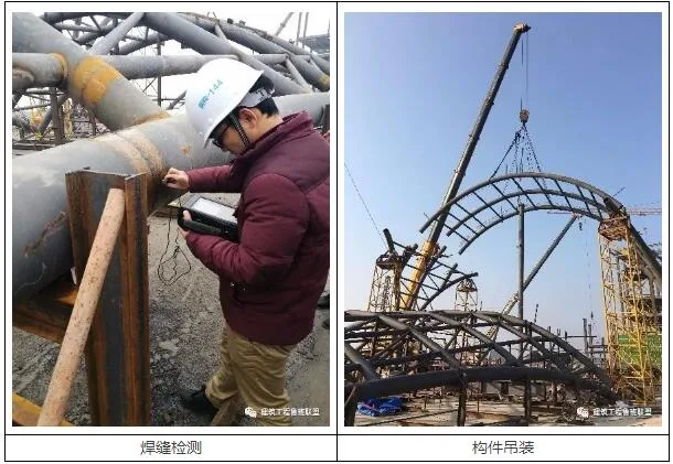
Component Hoisting
First, the pier columns on both sides and the steel beams of the platform between them are installed. Using a total station, positions for the supporting tire frames are marked and the frames placed accordingly. The supporting tire frames are secured with cable wind ropes and set at the lowest elevation of the circular tube at the mesh shell’s support nodes.
A 220-ton truck crane lifts each segmented mesh shell. After positioning, a total station monitors placement, and a jack fine-tunes coordinates—first horizontally, then vertically. Once positioned, horse plates are welded for fixation and elevation adjustments made using iron blocks underneath.
The lifting sequence is: 1st and 2nd blocks → 3rd block → 4th and 5th blocks → 6th and 7th blocks. After each segment is lifted, a 25-ton crane installs missing members between blocks. Following positioning, main and secondary members are welded before releasing temporary supports.
Support Frame Unloading
Before unloading, elevation measurements of the mesh shell are recorded. The supporting tire frames are unloaded synchronously and gradually, cutting the lower adjustment iron blocks by 1–2 cm increments. Each cut must be completed across all frames before proceeding to the next. Any anomalies during unloading require immediate suspension until resolved.
After unloading, elevation is re-measured to determine final deflection.
Simulation Analysis
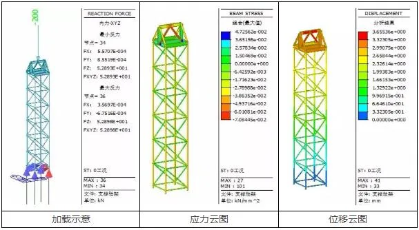
Simulation of the supporting tire frame under a 200 kN concentrated load shows a maximum stress of 70.85 MPa, which is below the yield strength of Q235B steel. The maximum stress ratio is 0.3, and the maximum displacement measures 3.65 mm, all meeting design specifications.
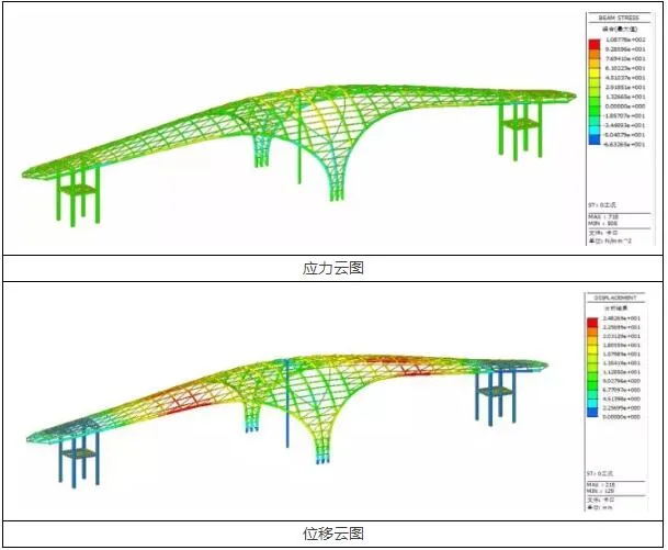
Simulation of mesh shell unloading using finite element analysis predicts a maximum stress of 108.78 MPa, below Q345B steel’s yield strength, with a stress ratio of 0.32. The maximum downward deflection of 25 mm occurs near the center of the shell’s “two wings.”
Grid Shell Block and Supporting Tire Frame Layout
Through meticulous planning and execution, the North Checkpoint project completed the main structure within 25 days, five days ahead of schedule. Weld seam quality control was excellent, with a first-pass acceptance rate exceeding 98%. The maximum deflection at the midpoint of the two wings after unloading was 23 mm, closely matching the calculated 25 mm and complying with design standards. No safety incidents occurred during construction.
This construction method for the hyperbolic arch single-layer steel pipe mesh shell at the North Checkpoint offers valuable insights for similar projects. It especially serves as a reference for the tight-schedule construction of single-layer steel tube mesh shells with complex hyperbolic arch intersecting nodes.


Must log in before commenting!
Sign Up