From a design perspective, this article analyzes the characteristics of steel structure residential systems and introduces the design concepts behind projects using special-shaped steel columns. It compares data on different damping ratios and foundation schemes used in frame structures, summarizes common design challenges and precautions, and offers alternative viewpoints on design standards.
1. Selection of Steel Structure Residential Systems
Based on existing steel structure residential buildings, the main structural types include:
1) Thin-walled steel composite wall panel system;
2) Pure frame system;
3) Frame-supported system;
4) Steel-reinforced concrete composite system;
5) Steel frame concrete seismic wall system, among others.
Each of these systems has its own unique features. The thin-walled steel composite wall panel system is particularly suited for standardized products. This system evolved from wall panel structures, where thin-walled steel column components are spaced approximately 600mm apart to form a vertical load-bearing framework. A support system is incorporated between steel sections to resist horizontal forces. Floor slabs are arranged as ribbed support structures aligned with vertical steel sections. Since the upper structure resembles a wall panel, the foundation typically consists of strip footings designed according to stress distribution, requiring relatively low foundation demands.
However, buildings using thin-walled steel composite wall panels tend to have dense structures, limiting the size and placement of openings such as doors, windows, and protruding architectural elements.
The other structural types can meet the design requirements for multi-story residential buildings but share a common issue: protruding beams and columns negatively impact interior aesthetics. Residential buildings differ significantly from office or industrial buildings, which often have fixed column grids and higher floor heights. In offices and factories, beams and columns occupy space in a way that feels appropriate and supports standard column grid layouts. In contrast, residential units have more variable layouts with smaller, irregular room openings, making regular steel frame arrangements challenging.
Due to the nature of steel, residential buildings typically employ frame or truss systems. While frame systems suit conventional residential buildings, steel frames must demonstrate clear advantages. If traditional frame structures cannot address specific residential challenges, then conventional steel frames will similarly face limitations.
Inspired by short-leg shear wall structures, designers have developed special-shaped steel columns to better accommodate architectural variations in steel structure residential buildings. Figure 1 illustrates two types of special-shaped steel column cross-sections, where the flange width corresponds to the building wall thickness minus the surface layer. The flanges of the frame beams and special-shaped steel columns are rigidly connected in all directions. Figure 2 shows detailed node connection designs.
Schematic diagram of special-shaped steel columns:
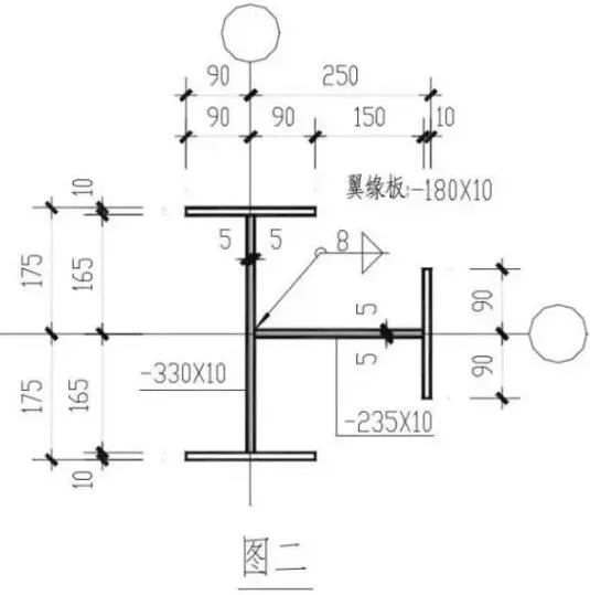
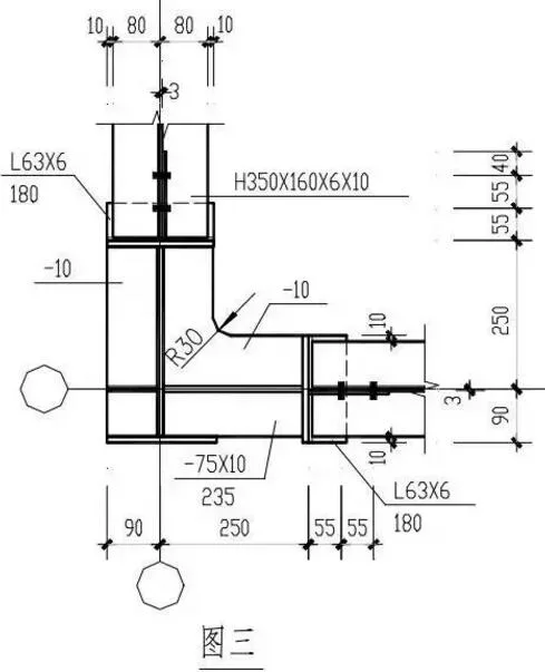
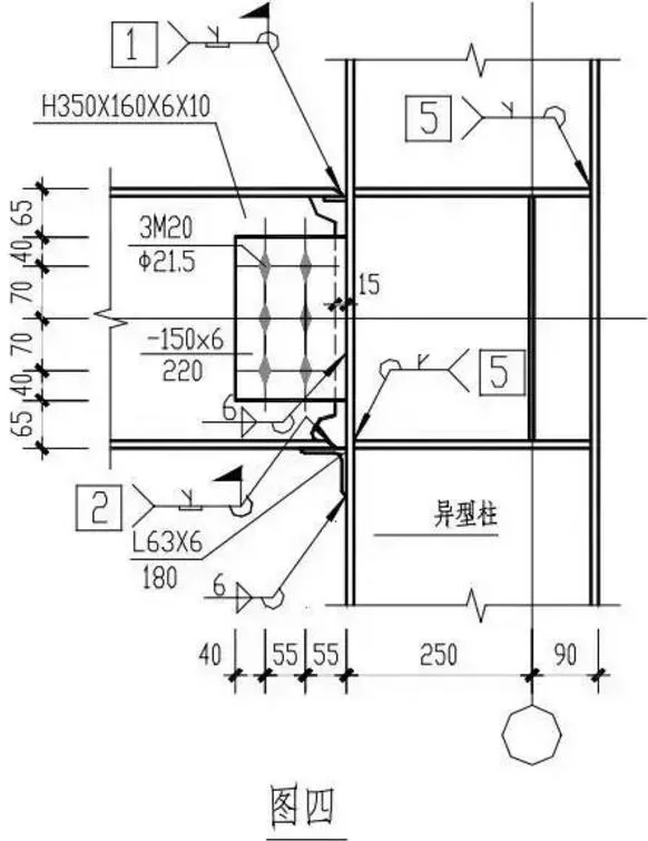
Detail drawing of special-shaped steel column beam-column nodes:
A three-story model room for a residential project was designed using a special-shaped steel column pure frame structure, complemented with block partition walls. Upon completion, both the interior and exterior appearances met expectations, closely resembling concrete shear wall residential buildings.
Special-shaped steel columns are commonly used in industrial plant design. In bent frame stress systems, these columns are often designed to be either double-axis or single-axis symmetrical along the primary load direction. The plant’s longitudinal direction is supported by a bracing system to resist horizontal forces, with tie rods and support components connected to the weak-axis centroid of the special-shaped columns. This arrangement simplifies structural design and analysis, especially using bar system software.
However, there are significant differences between applying special-shaped steel columns in residential buildings versus factory buildings. The following figure compares connection methods for beams and columns in factory buildings and residential buildings:
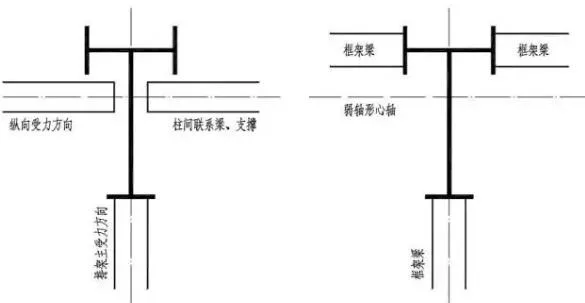
In residential buildings, the centroid axes of beam and column cross sections do not align, which deviates from conventional design principles. This misalignment poses challenges for bar system software calculations, which cannot handle off-axis forces effectively.
Compared to short-leg shear wall structures, irregular columns are essentially modified from larger rectangular frame columns or concrete walls into irregular sections with smaller cross-sectional areas, reducing sectional properties. In contrast, irregular steel columns add a T-shaped section to an I-beam, enhancing weak-axis sectional properties. Importantly, the rigid node connection between steel beams and the column’s weak axis flange is stronger than common designs where I-beam columns connect via outward-extending plates on the weak axis. This enhances the weak-axis stability of I-beam columns, improving structural safety.
It is generally believed that rigid connections on the weak axis of I-beam columns are unreliable. Many construction manuals recommend hinged frames, bracing systems, or steel pipe columns for weak-axis support. According to seismic codes:
“When a column is rigidly connected to beams in two perpendicular directions, a box section should be used. If rigidly connected in only one direction, an I-shaped section is recommended, with the column web plate placed in the plane of the rigid frame connection.”
Although the code does not explicitly forbid rigid weak-axis connections in I-beam columns, seismic node bearing capacity requirements generally prevent weak-axis rigid connections from meeting relevant clauses.
Compared to box columns, special-shaped I-beam columns offer easier node processing, simpler construction, and save steel. Compared to frame support systems, they reduce the number of supporting parts and can be flexibly integrated into residential walls, meeting architects’ preferences for hidden structural components.
Structural Analysis Challenges for Special-Shaped Steel Columns:
1) Evaluating full-section stress, especially whether adding T-shaped components on the weak axis effectively increases sectional properties, considering the offset distance of T-shaped parts from the axis. The increase proportion varies by steel column type.
2) Assessing local stability, which can be controlled by the width-to-thickness ratio of column plates according to specifications.
3) Overall force analysis at beam-column nodes where axes deviate cannot be addressed by standard rod system software. Ideally, finite element holistic modeling should be used, but this approach requires significant modeling effort.
Column Cross-Section Design Principles:
1) Conduct structural analysis using a square steel tube column model. Choose beam section sizes based on stress ratios approaching 0.9. Preliminarily select I-beam sections in both directions based on the square steel tube properties, ignoring web plate effects initially.
2) Analyze using the I-beam column model with T-shaped components integrated as decorative elements. Replace the stiffness effect of T-shaped components on the weak axis with flexible supports, calculate lateral displacements, and adjust I-beam cross-sections accordingly. Then finalize I-beam and flexible support layouts.
3) For seismic verification, select the single frame along the I-beam’s strong axis and check if unidirectional stresses meet requirements.
4) Manually calculate seismic bearing capacity at beam-column nodes, considering additional bending moments caused by off-axis effects during foundation design.
5) Perform standard design for ordinary I-beam and square steel tube columns using an unsupported frame system and calculate steel consumption to control upper and lower material limits for special-shaped columns.
This approach lacks precise formulas or provisions, and the overall impact of off-axis bending moments remains unquantified. Consequently, the author applied this method only in second- and third-floor residential buildings, avoiding use in taller structures. This special-shaped steel frame concept is proposed for critique and improvement.
2. Design Details
1. Damping Ratio Selection
When calculating the overall structure, select an appropriate damping ratio per seismic code requirements. Unless otherwise specified, use a damping ratio of 0.05. If different, seismic influence coefficients must be corrected accordingly. Table 1 lists typical damping ratios for various steel structure systems.
Table 1: Application Values of Damping Ratios for Different Structures
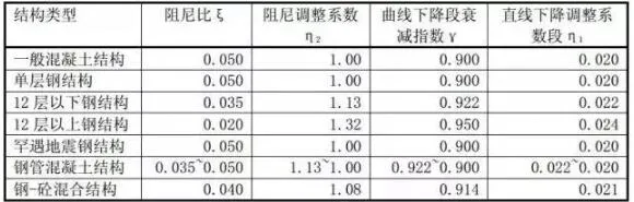
As seen, different steel structural systems have varying seismic influence coefficients. Incorrect damping ratio selection significantly affects design outcomes. For steel-reinforced concrete and hybrid structures, damping ratios should be chosen based on the relative proportions of steel and concrete. Generally, structures with lower overall stiffness require lower damping ratios.
2. Column Base Design
Common column base types include embedded, wrapped, and exposed bases. Exposed bases are often preferred in residential design for ease of on-site installation and positioning. The stiffness of an exposed column base arises from elastic or plastic deformation of the base plate, meaning overall structural deformation includes both steel structure deformation and base plate tensile deformation.
For example, internal force analyses often treat exposed bases as rigid. During design, inter-story drift limits should include a safety margin, and increased bending moments at the column top due to downward shifts of the base moment inflection point must be considered.
Node design requirements specify that the column base node’s ultimate bending capacity must exceed 1.2 times the full plastic bending capacity of the steel column (Wpnx · f) to prevent failure before the column during rare earthquakes. Typically, bolt diameters and weld sizes at the base are chosen based on reaction forces to ensure strength under frequent earthquakes.
The required section modulus for column base bending moments is generally smaller than that of the steel column itself (Wx). For example, with an H628X260X10X14 I-beam, 1.2 · Wpnx/Wx = 1.36, making it difficult to expose this design criterion. Embedded and wrapped bases more easily satisfy these requirements due to clearer force transmission, simpler calculations, ease of construction, and steel savings.
Plug-in column bases are simpler than embedded types but are generally considered less reliable. They are recommended for single-story steel factories but not for high-rise buildings. However, since industrial buildings often have greater story heights (10–30m) and heavier loads than residential buildings, plug-in bases can be appropriate for multi-story residential structures if design and calculations meet code requirements. New steel structure specifications now include design and construction regulations for plug-in bases.
3. Floor Design
Floor slabs may be precast, cast-in-place, or composite. When using prefabricated slabs, designers must consider additional bending moments caused by joint cracking due to temperature changes and load distribution. This involves combining bending stresses within the steel beam plane and outside the flange plane to meet allowable stress limits. Particular attention is needed when slabs are placed on the lower flange.
Profiled steel sheet composite floors are widely used in steel structure residential buildings. Comprehensive analysis should consider slab anisotropy, including whether slabs are continuous or simply supported, load transfer paths (unidirectional or bidirectional), and whether steel beams are combined with strong or weak edges, affecting stiffness. Floor slabs should avoid one-way concentration to promote a two-way load-bearing system for horizontal or vertical load distribution.
4. Beam-Column Rigid Connection Design
Rigid connections can be designed using standard methods or full-section bending design. When the bending capacity of the beam flange exceeds 70% of the entire section capacity, the standard design method suffices; otherwise, full-section bending design is required. In residential design, steel beams usually meet the former condition.
The standard design method assumes the flange resists bending moments while the web plate resists shear forces. Though easier, this method tends to be conservative.
In practice, achieving strong beam-column nodes with welded or bolted connections without additional measures is challenging. Reinforced node designs include welding wedge-shaped cover plates on beam flanges, adding stiffeners (“armpits”) under beam ends, or dog bone connections. However, these increase construction complexity.
A fourth method—widening the beam flange at the end—is not commonly featured in standard drawings but is often the most practical and straightforward when beam width is not a constraint.
3. Design Standards Issues
1. Concept of “Lightweight” Steel Structures
Recently, the term “lightweight portal frame house” has led many designers, including structural engineers, to associate steel structures with lightness. This sometimes results in using “light steel” for secondary building components without considering their impact on the main structure. In reality, “lightweight” refers to structures bearing relatively light loads. In residential design, steel structures do not reduce load standards. Whether steel or concrete is used, component effect analysis principles remain consistent.
2. Differences Between Multi-Story and High-Rise Steel Structure Design
According to codes, 12 floors is the threshold distinguishing multi-story from high-rise steel structures, affecting seismic adjustment coefficients, slenderness ratios, and component width-to-thickness ratios. High-rise buildings are defined as having 10 or more floors or exceeding 28 meters, including mixed structures. Internationally, high-rise thresholds often range between 8–11 floors or 25–30 meters.
This means China’s multi-story steel structures cover a broader height range than typical domestic or foreign standards. Multi-story and high-rise steel structures differ structurally and in seismic design parameters. For example, a 12-floor building with 4m floor heights reaches 48 meters, surpassing the 28m high-rise limit by 1.7 times. This raises issues, such as hybrid structures where concrete components must follow high-rise codes but steel components follow multi-story codes, resulting in dual standards.
3. Steel Structure Design Code
The latest code provides limited guidance for residential steel structures, continuing an industrial building design approach. For example, deformation limits are classified by factory components, with no subdivision for civil buildings. Temperature range requirements are uniform for bent frame structures, without addressing longitudinal versus transverse load-bearing systems or steel-concrete composites.
Clause 8.1.4 mandates reliable support systems for structural forms, stating unsupported pure frame steel structures should not be used. This contradicts practical applications where support needs depend on design requirements. Although this clause is mandatory, its strict enforcement warrants discussion. Civil buildings differ from industrial ones in usage and structural systems and should be treated accordingly.
Compared to regulations that increasingly emphasize seismic resistance, the new code only generally references seismic compliance. This downplays seismic design importance in steel structures. Internationally, seismic design of steel frames gained attention after major earthquakes, with research and publications available. It is questionable that China’s seismic codes impose different measures based on seismic intensity but lack differentiated seismic requirements for steel structures.
4. Design of Steel Structure Residential Buildings Should Respect Fundamental Residential Requirements
Steel structure housing represents a key future development direction, but steel serves primarily as the load-bearing and service system, not the main component of building use. Design should first follow general residential building principles, then utilize steel’s advantages.
Steel structure residential projects that focus solely on steel use without ensuring living comfort and human-centric design lack market appeal. For example, public buildings, sports venues, and industrial factories better showcase steel’s construction strengths.
In recent years, this shift in application has become increasingly apparent.


Must log in before commenting!
Sign Up