1. Process Flow
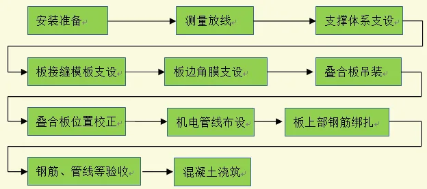
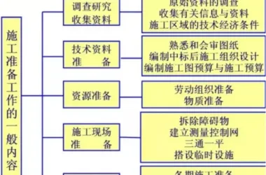
2. Installation Preparation
1) Review the construction drawings to identify the types of composite panel components. Determine their installation positions and assign numbers to the lifting sequence of the panels.
2) At the construction site, remove any hidden column stirrups, horizontal ladder bars, positioning bars, or beam irons that may obstruct the outward extension of steel bars during panel lifting. These should be restored to their original state once the panels are installed.
3. Measurement and Layout
1) Using the layout diagram for the independent support system, mark the support points on the floor slab.
2) According to the detailed prefabrication drawings, mark the edges and centerlines of the composite panels on the walls. Also mark a horizontal reference line at +1 meter and the panel position lines on the shear wall surface. Clear markings must be made to control the installation elevation and plan position of the panels. Verify all control lines carefully.
4. Establishing the Support System
1) The support system beneath the composite panels consists of aluminum alloy I-beams, brackets, independent prefabricated steel columns, and stable tripods.
2) Place the steel supports, I-beams, and brackets as per the layout plan. Adjust them to the design elevation and mark with a small white line, leveling with a spirit level. Install the main keel and secure the I-beam using adjustable wooden U-shaped beam brackets.
Support points should be set under the laminated floor slab according to specifications, with spacing based on the support system layout. Adjust support heights to the design elevation before placing the slab.
5. Formwork Support for Laminated Panel Joints
1) Joints between laminated boards are typically post-pour strips about 300mm wide. The joint formwork is made from wooden plywood, no longer than 1.5 meters for ease of handling and installation.
2) To prevent grout leakage at the joints, a 3mm thick plywood lining is installed on the formwork surface within the joint area.
3) The formwork support system uses a single-row bowl buckle frame connected with steel pipes to form a stable structure.
6. Limb Corneal Support
The corneal support is constructed from 12mm plywood, reinforced at the back with 50 x 100 mm square timber, fastened using #14 threaded screws.
7. Lifting and Positioning of Composite Panels
When lifting composite panels, it is important to minimize bending moments caused by the panel’s own weight in the non-prestressed direction. A 3-meter hemp rope is used as a traction rope to assist with positioning during lifting.
1) Lifting points must be determined based on detailed design drawings or markings on prefabricated components delivered to the site. These positions must not be altered arbitrarily.
2) The number of suspension points depends on panel size: panels smaller than 4000mm on both length and width have 4 suspension points at the corners. Larger panels have 6 to 8 suspension points symmetrically placed to ensure even load distribution and smooth lifting.
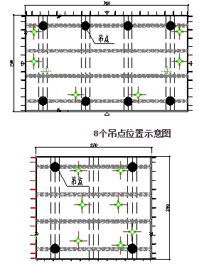
Schematic diagram showing the positions of 4 suspension points
3) Before full lifting, perform a trial lift stopping approximately 50 cm above ground level. Check the tension on the steel wire rope and hook to ensure the panel remains level. Then proceed to lift the panel above the working layer. The sling’s horizontal angle must be at least 60°, meaning the steel wire rope length should be no less than 3 meters for each panel.
4) When positioning the panel, install it vertically from top to bottom, pausing briefly about 30 cm above the working layer. Workers should support the slab, adjusting its direction to align the panel edge with the placement line on the wall. Take care to avoid interference between the panel’s reserved steel bars and those on the wall. Lower the panel steadily and slowly—rapid or forceful placement is strictly prohibited to prevent surface damage such as shaking, folding, or cracking.
Lifting must be halted if wind speeds exceed level 5.
5) When adjusting the panel’s position, use small wooden blocks as cushions. Avoid using pry bars directly to prevent damage to edges and corners. Ensure the panel length meets requirements, with allowable deviation no greater than 5 millimeters. Wrap pry bar ends with cotton cloth to protect the laminated surface.
6) After installing the laminated panel, perform standard calibration and adjust the adjustable supports beneath the slab accordingly.
8. Installation of Mechanical and Electrical Pipelines
Mechanical and electrical wiring boxes and pipelines within the composite panel area should be arranged following the detailed design drawings.
9. Binding Steel Bars on the Upper Surface of the Laminated Board
After laying and cleaning the standby power lines, bind the steel bars according to the spacing control lines above the laminated board. Ensure steel bar overlaps and spacing comply with design specifications. Use the steel bars of the laminated panel truss as supports (“horse stools”) for the upper steel bars to maintain the required protective concrete cover thickness.
10. Concrete Pouring
Once the steel bar inspection passes and the composite surface is cleaned, proceed with concrete pouring.
1) Thoroughly clean and wet the laminated board surface before pouring.
2) To ensure uniform stress distribution between the composite panel and support system, pour concrete from the center outward continuously without interruption. Use a vibrating rod to compact the concrete thoroughly.
3) Control slab thickness according to the elevation control line. Level the concrete with a 2-meter scraper, then finish and roughen the surface as required.
4) Immediately cure the concrete after pouring, following prefabricated assembly curing methods. The curing period should be no less than 7 days.
11. Quality Standards
After installing the laminated panels, the allowable deviation in component installation dimensions must meet specification requirements.
Inspection should be conducted in batches, divided by floor and construction section. All items within a batch must be thoroughly checked.


Must log in before commenting!
Sign Up