Prefabricated buildings offer an effective solution for advancing residential industrialization, as well as promoting energy conservation and emission reduction in construction. These buildings are manufactured off-site in factories and assembled on-site, which not only supports industrialized housing but also saves energy and resources, minimizes the environmental impact of construction waste, and reduces site restrictions.
By the late 20th century, China emphasized the “four conservation environmental protection” goals—energy, water, land, financial conservation, and environmental protection—to foster the development of green, energy-efficient buildings. Extensive research focused on key components of prefabricated concrete structures, such as laminated wall panels, sandwich wall panels, and solid wall panels, with particular attention to sandwich wall panels due to their superior structural and insulation properties.
In 2007, Zhao Ruxiang utilized the finite element software ANSYS to analyze factors influencing the bearing capacity of polystyrene composite concrete walls. The study revealed that increased concrete slab thickness and reinforcement quantity correlate with higher wall panel bearing capacity. Later, in 2012, Hu Xiaojing conducted bending tests on five full-scale energy-saving composite concrete wall panels, demonstrating that thicker concrete panels and thicker sandwich layers enhance bending stiffness and capacity. In 2015, Xue Weichen and colleagues from Tongji University experimentally examined the tensile and shear properties of 60 FRP connectors in prefabricated sandwich insulation walls after accelerated aging. Their results showed a decline in tensile strength of FRP connectors over time in simulated concrete environments at 40°C and 60°C.
International research on prefabricated concrete wall panels is also abundant. For example, in 2012, Fabrizio Gara and others performed full-scale tests on precast concrete wall panels with various aspect ratios under axial and eccentric compression, finding an inverse relationship between aspect ratio and ultimate bearing capacity. In 2015, Fengtao Bai and his team proposed a small displacement theory for foam insulated concrete sandwich wall panels based on composite material principles, confirming the accuracy of this theoretical approach.
This article focuses on a Total Bolt Connection Prefabricated Concrete Structure (BPC structure), designed to overcome limitations of existing prefabricated concrete systems.
The BPC structure comprises prefabricated concrete sandwich wall panels, wall columns, cushion blocks, door and window frames, prestressed floor slabs, and roof panels or light steel roofs. Each sandwich wall panel features two 60mm-thick concrete slabs enclosing a 100mm-thick insulation layer. The prestressed concrete floor or roof slabs consist of multiple standard prefabricated concrete sections connected by prestressed steel bars. All components form a standardized industrial series, manufactured off-site and assembled on-site using bolts, as illustrated in Figure 1 and Figure 2:
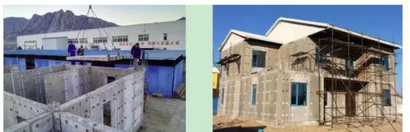
Compared to other prefabricated concrete systems, the BPC structure’s fully bolted connections facilitate standardized, industrialized components and enable simple, flexible on-site installation without wet work. It integrates structural insulation, allows easy installation of reserved pipelines, and offers a low overall cost. This approach aligns with the national “Outline for the Modernization of the Construction Industry” and shows promising applications in low-rise and mid-rise villas, office buildings, dormitories, inpatient departments, and temporary structures.
Experimental studies were conducted to evaluate the vertical bearing capacity of a standard 1200mm-wide precast concrete sandwich wall panel within the BPC structure. The mechanical performance, ultimate bearing capacity, and failure modes were investigated and compared to finite element analysis results, which showed good agreement, providing a foundation for broader adoption of BPC structures.
1. Test Specimen
Figure 3 depicts the schematic of the 1200mm-wide, 3000mm-high, and 220mm-thick sandwich wall panel used in the BPC structure. Various building wall widths can be constructed by combining these standard panels flexibly.
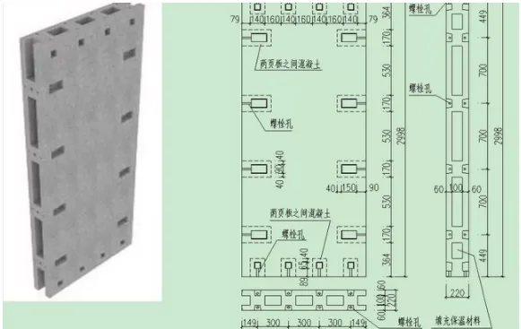
Figure 4 illustrates detailed design features of the 1200mm-wide standard wall panel. Each panel consists of two 60mm-thick precast concrete slabs sandwiching a 100mm insulation layer. Along the height of each vertical panel, four slot holes measuring 150mm (width) × 80mm (height) × 60mm (depth) are reserved on both sides to accommodate bolt connections between adjacent panels. Similarly, slot holes of 60mm (width) × 65mm (height) × 60mm (depth) are spaced at 300mm intervals at the panel’s top and bottom edges for bolted connections through cushion blocks or floor slabs to upper panels or foundations. At these slot hole locations, the two prefab panels are joined using concrete, as indicated by the dashed lines in Figure 4. Low-carbon cold drawn steel wires (Φ4mm), spaced 100mm apart in both directions, are evenly distributed within the panels, with denser arrangements at panel connections.
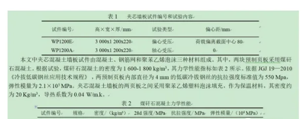
Two specimens were prepared for load-bearing capacity testing of BPC sandwich wall panels, considering axial and eccentric compression scenarios. Table 1 summarizes the specimen numbers and test parameters.
2. Experimental Apparatus
The two sandwich wall panel specimens were tested using a 500-ton press, applying axial compression and eccentric loading.
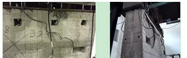
To replicate real-world conditions, HM350 × 250 × 9 × 14 steel sections were placed at the top and bottom of the specimens. The flanges connected to the panels were perforated and bolted, with stiffening plates positioned on both sides of each bolt, as shown in Figure 5. Figure 6 presents photos from the on-site tests.
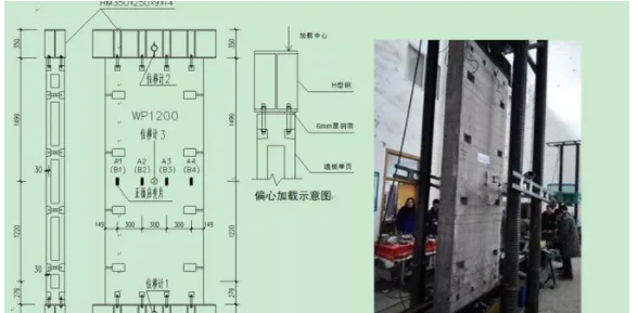
For eccentric compression tests, a 6mm-thick steel strip matching the width of a single panel was inserted between the H-beam flange and the panel. The press was aligned with the center of the single panel to ensure that the load was transmitted exclusively to it, as depicted in Figure 5.
Strain gauges were strategically placed on both outer surfaces of the wall panels to monitor strain during loading. For specimens WP1200E and WP1200A, four gauges were vertically arranged on the front (A1–A4) and back (B1–B4) surfaces, with their locations shown in Figure 5.
Displacement gauges were set up to measure vertical and horizontal deformations: two gauges (No.1 and No.2) were placed at the center of the lower surface of the upper flange and the upper surface of the lower flange of the H-shaped steel at the specimen’s ends, respectively, while gauge No.3 monitored horizontal displacement at the panel’s midpoint on the front surface, as illustrated in Figure 5.
Before testing, finite element analysis estimated the specimens’ ultimate bearing capacities. Specimens were then carefully aligned on the press base, first geometrically, then physically. Physical alignment loads were set to 10% of the estimated ultimate capacity, and alignment was considered complete once strain gauge readings across layers differed by less than 10%.
3. Experimental Results and Analysis
3.1 Observations and Ultimate Bearing Capacity
During axial compression testing of specimen WP1200A, no noticeable effects were observed under 500 kN load. At 750 kN and 1250 kN, faint “sizzling” sounds occurred without visible damage. When the load reached 1700 kN, muffled sounds accompanied the appearance of concrete cracks and spalling at the specimen’s top. At 2220 kN, concrete detachment was evident on the upper side, and at 2400 kN, crushing and failure of the upper concrete occurred. The ultimate load was recorded as 2426.5 kN.
For the eccentric compression specimen WP1200E, initial loading produced no obvious effects. At 660 kN, faint falling concrete sounds were heard. At 950 kN, continuous cracking noises emerged, escalating sharply at 1128 kN. Failure occurred at 1130 kN when large concrete fragments detached near bolt connection holes at the specimen’s upper left corner. The ultimate load was 1131.7 kN.
Key observations include:
- The vertical axial load-bearing capacity of the prefabricated concrete sandwich wall panel (WP1200A) reached 2426.5 kN, corresponding to a compressive stress of 16.85 N/mm², demonstrating its suitability for load-bearing walls in low-rise and mid-rise buildings.
- The eccentric compression specimen (WP1200E) achieved an ultimate load of 1131.7 kN, about 46.6% of WP1200A’s capacity, indicating that sandwich panels can support load-bearing walls under eccentric compression, albeit with reduced strength.
- Both axial and eccentric compression tests exhibited brittle failure modes, with damage concentrated near the specimen ends and bolt holes, characterized by peeling of the concrete surface.
3.2 Load-Strain Relationship
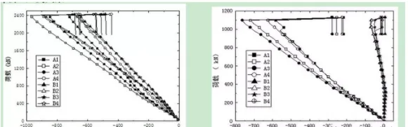
Figures 9 and 10 display load-strain curves at mid-height measuring points (A1-A4 and B1-B4) on the two specimen surfaces. Findings include:
- Strain gauges symmetrically positioned on the same surface or corresponding front and back locations showed consistent strain trends relative to load, confirming good specimen alignment prior to testing. Minor discrepancies among gauges are attributed to stress redistribution near bolt holes.
- For WP1200A, the load-strain relationship was linear up to failure, with maximum strains between 650 and 950 microstrain. The failure was sudden, with no significant elastic-plastic deformation, indicating typical brittle behavior.
- In WP1200E, strain increased linearly on the loaded panel with maximum values between 550 and 750 microstrain before brittle failure. The non-loaded panel’s strain remained nearly constant, indicating the load was primarily carried by the loaded side.
3.3 Load-Displacement Curve
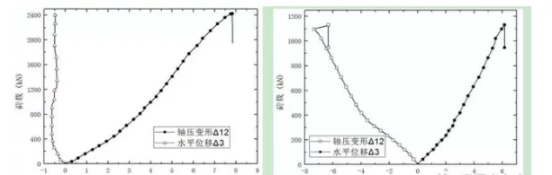
Figures 11 and 12 illustrate the relationship between applied load and axial compression displacement (Δ12, measured between displacement gauges 1 and 2), along with horizontal displacement (Δ3) at mid-height (gauge 3). Observations are:
- For WP1200A, the load-axial displacement curve was almost linear, with a maximum compression displacement of 7.84 mm and no evident plastic deformation prior to failure, confirming brittle behavior. Horizontal displacement remained negligible, indicating deformation was primarily axial.
- WP1200E showed a similar linear trend in both axial and horizontal displacement curves, with maximum Δ12 and Δ3 of 6.14 mm and 7.40 mm, respectively. The horizontal displacement reflects the effect of eccentric loading, with failure also characterized as brittle.
4. Finite Element Model Development
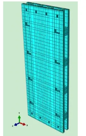
The prefabricated sandwich concrete wall panel specimens were modeled and analyzed using the finite element software ABAQUS. Concrete was represented with a damage plasticity constitutive model, using C3D8R reduced integration solid elements. Material parameters are detailed in Table 2 and reference __AI_S_SC0_. The internal steel mesh consisted of 4mm diameter low-carbon cold drawn steel bars with an elastic modulus of E = 2.1 × 10⁵ MPa and yield strength of 550 MPa, modeled as truss elements (T3D2). Figure 13 shows the mesh of the wall panel model.
Steel beams and bolts at the panel ends were omitted from the model. Instead, the steel mesh was embedded in the concrete panels via embeddedRegion constraints.
For specimen WP1200A, axial load was applied concentrically at the reference point coupled to the top surfaces of both panels. The bottom surfaces were fully constrained in translation and rotation, while the top surfaces allowed vertical movement and in-plane rotation. For WP1200E, eccentric load was applied to the reference point coupled to the top surface of one panel only. The bottom surfaces were fully constrained, and the top surface of the loaded panel allowed vertical displacement and in-plane rotation, while the other panel’s top surface was free.
5. Finite Element Analysis Results and Comparison
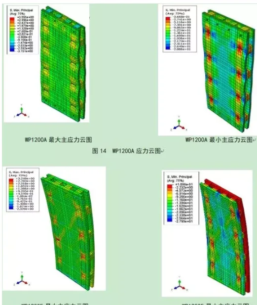
Figures 14 and 15 present principal stress distributions and deformation maps at failure for specimens subjected to axial and eccentric loads, respectively:
- In WP1200A, maximum principal tensile stresses (3.56 N/mm²) concentrate around horizontal bolt holes on the concrete surface, the middle top between panels, and the concrete connection blocks, consistent with initial crack locations observed experimentally (Figure 7).
- Maximum principal compressive stresses (28.86 N/mm²) in WP1200A concentrate near the ends of horizontal bolt holes, with vertical wavy deformation patterns along the panels.
- WP1200E exhibited significant bending upon failure. The non-loaded panel experienced tension with a maximum principal tensile stress of 1.10 N/mm², while the loaded panel’s tensile stress peaked at 3.25 N/mm² near horizontal bolt holes and connection blocks, matching observed crack locations (Figure 8). Maximum compressive stresses (28.00 N/mm²) localized in the loaded panel’s center and edges.
These results highlight that bolt holes, especially horizontally oriented ones, induce stress concentrations and redistribution under vertical loads, which contribute to panel failure. The concrete connection blocks between panels play a critical role in ensuring joint integrity and enhancing load-bearing capacity.
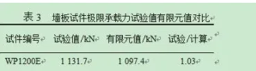
Table 3 compares experimental and finite element predicted ultimate loads for both specimens under axial and eccentric loading. The ratios of experimental to calculated values were 1.03 for WP1200A and 0.99 for WP1200E, demonstrating strong agreement and validating the finite element modeling approach.
6. Conclusion
This study investigated a fully bolted prefabricated concrete structure, focusing on the axial and eccentric vertical load-bearing capacity of a standard 1200mm-wide, 3m-high precast concrete sandwich wall panel. Based on experimental data and finite element analysis, key conclusions are:
- Both axial and eccentric compression tests exhibited brittle failure modes. WP1200A failed by crushing of the upper concrete with an ultimate load of 2426.5 kN, while WP1200E experienced concrete spalling near bolt holes at 1131.7 kN.
- Strain measurements indicated a linear load-strain relationship up to failure, with maximum strains between 650–950 microstrain for axial compression and 550–750 microstrain for eccentric compression on the loaded panel. The non-loaded panel in eccentric tests showed negligible strain, confirming load concentration.
- Load-displacement curves were essentially linear, reaffirming the brittle failure behavior without observable plastic deformation.
- Finite element analysis identified stress concentrations near horizontal bolt holes and concrete connection blocks, matching observed failure locations and confirming model accuracy.
- The close agreement between experimental and FEA ultimate load values (ratios of 1.03 and 0.99) validates the modeling methods used.
- Stress redistribution caused by bolt holes, particularly horizontal ones, is a critical factor in panel failure. The concrete connection blocks between panels are essential for joint performance and improving load capacity.


Must log in before commenting!
Sign Up