EPC Implementation Characteristics
Concept Phase
During the concept phase, the building layout must account for component segmentation, simplification, and modularization.
The selection of prefabricated component types requires a comprehensive evaluation of both production and construction costs.
Expansion and Construction Drawing Stage
This stage is divided into two main areas: architecture and mechanical & electrical engineering. The architectural part is further split into facade and structure.
For the facade, it is essential to ensure that the size of prefabricated exterior wall panels does not exceed 3.3 meters in any direction.
The structure is divided into three components: cast-in-place columns, composite beams, and composite panels.
Cast-in-Place Columns
When positioning and reducing the cross-section of columns, consider the specifications of the composite beams.
The recommended net spacing between longitudinal bars in cast-in-place columns connected to prefabricated beams is at least 100mm.
Longitudinal bar positioning should be provided for cast-in-place columns connected to prefabricated beams.
Composite Beams
The beam layout should take into account the impact on floor slab specifications.
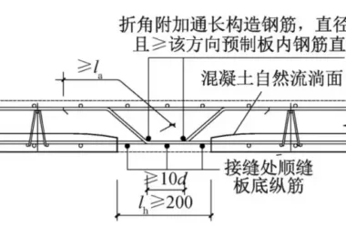
Composite beams should avoid diagonal steel bars protruding from the prefabricated surface.
It is recommended to extend the waist reinforcement of composite beams beyond the prefabricated surface.
Where stress requirements allow, partial truncation of the bottom reinforcement at the support is advised.
The steel bars entering the support should be no more than two rows, ideally only one row.
The recommended net spacing between steel bars in beams is at least 50mm.
If mechanical joints or anchoring plates are used, steel bar spacing must comply with assembled structure requirements.
Laminated Board
For laminated floor slabs, it is recommended to space the bottom bars in multiples of 50mm.
Mechatronics Implementation Characteristics
Key considerations include:
- Reserved holes and embedded parts should never be placed at the joints of prefabricated components. For example, junction boxes on floor slabs or wall panels must avoid these joints.
- Pipelines passing through floor slabs or walls should not intersect with prefabricated component joints.
- Embedded parts for pipeline supports and hangers must not be located at prefabricated component joints.
Electrical facilities with complex wiring, such as equipotential boxes and strong/weak current boxes, are not recommended for installation on prefabricated components.
For pipelines passing through beams, the casing top should be at least 50mm away from the underside of the floor slab.
Deepening the Design Phase
This phase involves two parts: confirming reserved pre-embedded points and preparing detailed drawings.
Confirmation of reserved and embedded points includes the following:
- Verification of reserved and embedded nodes and materials for door and window frames.
- Mechanical and electrical reservation principles and material confirmation.
- Reserved and pre-embedded nodes for railings, with material confirmation.
- Confirmation of principles for reserved and embedded construction materials, including tower crane wall supports, personnel and cargo elevator wall supports, construction layout holes, and formwork reinforcement.
- Verification of reserved and embedded nodes and materials for lightning protection and grounding.
Project Highlights and Challenges
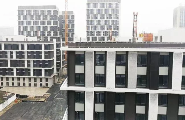
Selection of Artistic Concrete Veneer Integrated Prefabricated Exterior Walls
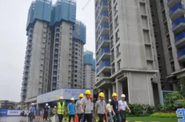
Located at the intersection of Qishen Road and Xiuwen Road, this landmark project in Xinzhuang Town demands a high-quality exterior facade.
The integrated prefabricated exterior wall with artistic concrete veneer offers clear texture and smooth lines, presenting significant advantages over traditional coatings in terms of facade appearance, as recognized by BIM engineers.
Therefore, the project employs prefabricated exterior walls integrated with decorative elements. These elements are formed using silicone molds, divided into coarse and fine patterns, which shape the smooth lines and textures, creating a dynamic and elegant artistic effect.
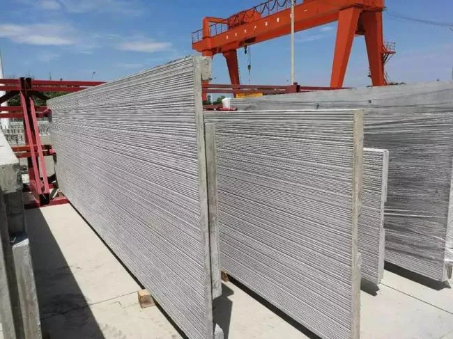
Decorative Integrated Prefabricated Exterior Wall Hoisting
The prefabricated exterior walls measure approximately 1.5 to 3.0 meters in width, 4.5 to 6.0 meters in height, and 120mm in thickness.
Considering road transportation height limits and the need to protect finished exterior surfaces, the panels are transported stacked in a side-standing position.
This method requires an additional flipping process during installation compared to standard prefabricated wall panels.
Due to the integrated molding of finishes, protection requirements are high, making the selection of flipping methods critical.
Three flipping schemes were developed early in the project:
Option 1
Excavate a sand pit measuring 4.0m by 7.0m and 1.0m deep at the edge of each building’s storage yard, filled with 800mm of fine sand for panel flipping.
Option 2
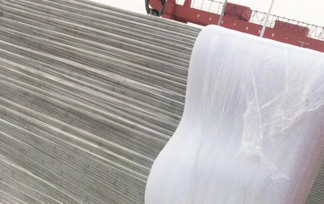
Use waste tires stacked at the edge of each building’s yard as a flipping area. Coarse fiber fabric is laid over the tires to maintain cleanliness and improve friction. The on-site setup is shown below.
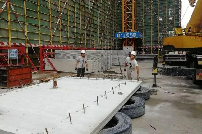
On-site construction diagram for flipping using waste tires.
Option 3
Use a flipping machine, as illustrated in the diagram below. Panels are first placed on the flipping platform, then flipped before lifting.
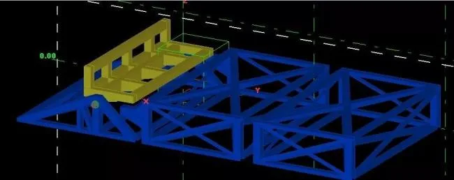
Diagram of the flipping machine in operation.
After thorough comparison and experimental verification, Option 1 was ruled out due to site limitations, and Option 3 was considered costly and risky. Therefore, Option 2 was selected.
Component Protection
During fixing, transporting, and flipping, areas in contact with decorative patterns on both the exterior and interior surfaces must be protected with pearl cotton.
To prevent contamination during subsequent construction, the entire panel is wrapped with protective film.
The process involves wrapping the entire panel with film first, then reinforcing contact areas with pearl cotton.
Waterproofing of Decorative Integrated Prefabricated Exterior Walls
The project applies BIM models in design and combines structural and material waterproofing methods.
On-site control is emphasized to ensure 100% water testing of wall panel joints, achieving full compliance.
Application of BIM Technology
BIM technology is used throughout the consulting and design phases of prefabricated components.
By presenting the building in 3D, the appearance becomes clearer and more vivid, node collision detection is simplified, and component information accuracy is improved.
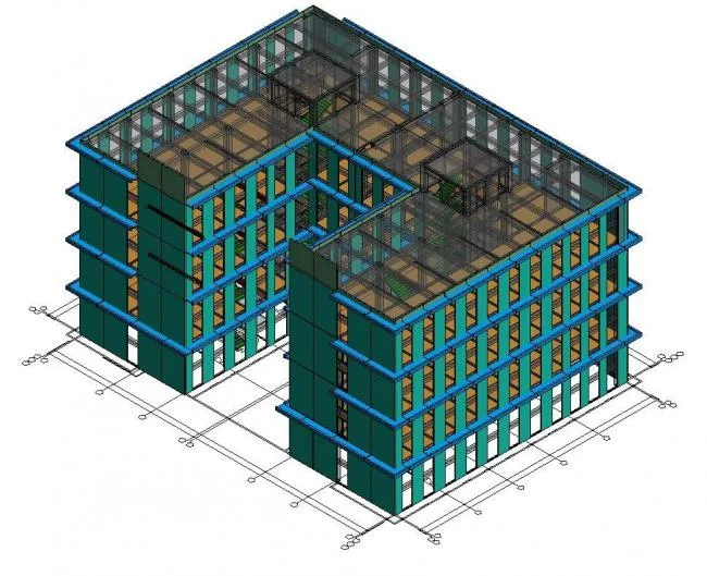
Building 5 BIM Model Diagram


Must log in before commenting!
Sign Up