To effectively implement the directives outlined in the Notice on Pilot Inspection of Implementation of Compulsory Standards for Engineering Construction issued by the Ministry of Housing and Urban-Rural Development (Jianbanbiaohan [2009] No. 183), and the Work Plan for Pilot Inspection of Implementation of Compulsory Standards for Engineering Construction by the Construction Bureau of the Xinjiang Production and Construction Corps (Bingjianfa [2009] No. 87), the First Construction Department of the Xinjiang Production and Construction Corps has developed a set of measures aimed at improving construction technology and quality.
These measures align with existing laws and regulations such as the Regulations on Quality Management of Construction Projects, Regulations on Energy Conservation of Civil Buildings, Regulations on Safety Production Management of Construction Projects, and Regulations on Supervision of Implementation of Compulsory Standards for Engineering Construction. They are designed to strengthen the enforcement of compulsory standards for engineering construction, enhancing the quality, safety, and energy conservation standards in building projects.
Below are the key measures classified and compiled to address critical technical challenges and weak links observed in recent construction projects:
1. Foundation Elevation and Masonry
When there is a difference in base elevation, the foundation should be sloped gradually in steps at a ratio of 1:2. Foundation masonry must be constructed starting from the lower part, progressing from higher to lower elevations. Unless otherwise specified in design documents, the overlap length should be at least equal to the height of the foundation’s expanded part and no less than 500mm.
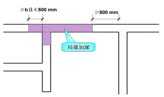
Partial lifting platform and reserved part of the foundation
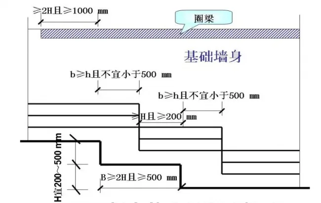
Schematic diagram of foundation masonry at different elevations
2. Brick Masonry Corners and Junctions
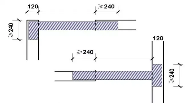
Corners and junctions in brick masonry must be constructed simultaneously. Separate construction of inner and outer walls without reliable measures is strictly prohibited. For unavoidable temporary breaks, diagonal joints should be used, with the horizontal projection length no less than two-thirds of the wall height (or half for porous bricks). If design documents do not specify reliable measures for dividing inner and outer walls, a C20 cast-in-place concrete ring beam (120mm x wall width) must be installed mid-wall. This ring beam should include longitudinal reinforcement of 4 Φ12 bars and hoop reinforcement of Φ6 at 200mm spacing, with vertical spacing not exceeding 1.2m. The ring beam must be anchored into adjacent structural columns or walls, with anchorage length of at least 2.5m on each side of the break.
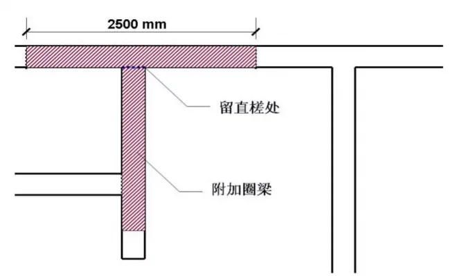
Construction structure of internal and external wall masonry
3. Wall Tie-in for Infill and Partition Walls
For infill or partition walls longer than 5m or in seismic zones rated 8-9 degrees, the wall top must be securely tied to the floor slab or beam. If no tie design is specified, a C20 fine aggregate concrete short column matching the wall thickness (minimum 150mm width and 200mm height) should be poured atop the wall at least seven days after masonry completion. Each short column must contain at least one Φ10 steel bar, spaced no more than 1.2m apart, and firmly connected to the structural frame.
4. Exterior Door and Window Installation
Doors and windows must be firmly installed without using nails to fix them onto masonry. If no concrete frame surrounds the openings, concrete blocks (minimum 115mm × 115mm × 90mm, strength grade C20) should be embedded in the masonry. All spacing must comply with acceptance and installation standards.
5. Reinforcement Near Door and Window Openings
In seismic zones rated 8 degrees, if the minimum width of load-bearing masonry window walls or the distance between wall ends and openings is less than 1.2m, local reinforcement is required. When design specifications are lacking, a concrete structural column (180mm x wall thickness, grade C20) can be installed at the opening edges, reinforced with 4 Φ12 longitudinal bars and Φ6 hoop bars at 200mm spacing, anchored vertically into beams and floors.
6. Use of Brick Beams at Openings
Unreinforced brick beams must not be used above doors and windows. The beam support length should be at least 240mm for seismic zones 6-8 degrees and 360mm for 9 degrees. If the support length is insufficient, reliable anchoring must be implemented.
Construction of short supports for lintels
7. Beam Support at External Corners in High Seismic Zones
In seismic zones rated 8 or 9 degrees, beam supports at external corners of walls in stairwells and lobbies must be at least 500mm long and securely connected to ring beams or floor slabs.
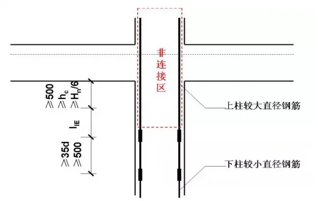
8. Steel Bar Anchorage in Columns with Variable Diameters
If steel bars in upper columns are larger in diameter than those in lower columns within seismic resistant frame structures, the minimum cut length of upper bars extending downward from beam bottoms must be at least llE plus the greater of Hn/6, hc, or 500mm. Additional quality requirements for steel bar connections must be met.
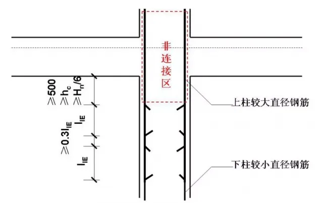
Construction when the diameter of the upper column reinforcement is larger than that of the lower column reinforcement
9. Anchorage Length for Positive Bending Moment Steel Bars
For cast-in-place slabs, the anchorage length of positive bending moment steel bars extending into cast-in-place concrete supports at mid-span should be at least 100mm or reach the support centerline, whichever is greater. For masonry supports, the anchorage length must be no less than 120mm or the greater of the slab height or centerline. When temperature shrinkage stresses are significant, anchorage length should be increased to at least 15 times the bar diameter (≥ 15d). For slabs with edge beams (ring beams), anchorage length of negative bending moment steel bars should be at least la.
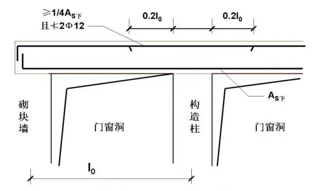
10. Longitudinal Steel Reinforcement in Partially Constrained Beam Ends
When beam ends are partially constrained but calculated as simply supported, longitudinal steel bars must be placed on the upper support area with a cross-sectional area not less than one-quarter of that required for tensile steel bars in the mid and lower beam span. There must be at least two Φ12 steel bars. The length of these bars extending from the support edge into the span should be no less than 0.2 times the beam length (0.2l0).
Construction of simply supported and embedded supports for lintels
11. Cast-in-Place Stair Construction
Stairs should be constructed simultaneously with the main structure, avoiding horizontal grooves inside walls. Construction joints on stair treads must be located within the middle third of the tread span, with the joint positioned 50% to 66% of the tread width from the leading edge.
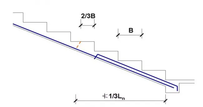
Construction joint retention structure for stair treads
12. Formwork Removal for Cast-in-Place Components
Removal of bottom formwork and support must comply with the Code for Acceptance of Construction Quality of Concrete Structures. The concrete must reach a minimum strength of 2.5 MPa before side formwork removal, ensuring no damage to surfaces or edges.
Column wall formwork reinforced with high-strength screws ensures precise column cross-section.
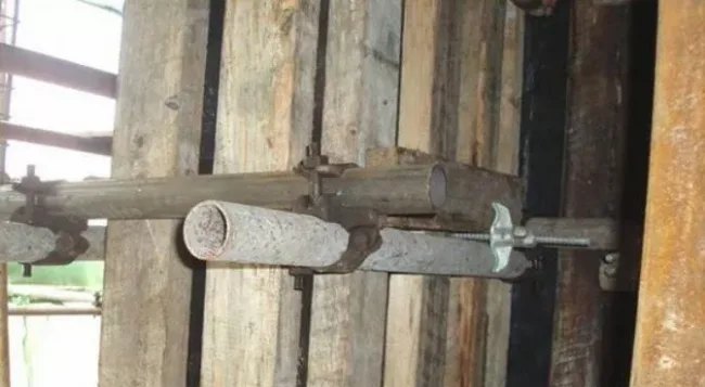
13. Steel Bar Displacement Limits
The maximum displacement of steel bars in shear walls and frame columns must not exceed 35mm. If exceeded, a technical remediation plan must be submitted for approval. Unauthorized cutting or hot bending of displaced steel bars is strictly prohibited.
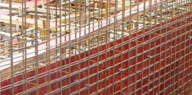
Vertical steel bars are positioned using clamp-type plastic pads.
14. Roof Insulation Moisture Control
The moisture content in the roof insulation layer must meet design requirements. If drying is difficult, coordination with the design unit is necessary to implement an exhaust roof system. In the absence of specific design requirements, metal exhaust pipes should be installed with spacing not exceeding 6m both longitudinally and transversely. Pipe diameters should range between 20-50mm to ensure effective exhaust while avoiding thermal bridging. Exhaust outlets must be bent downward and positioned at least 300mm above the roof surface.
15. Elevation Differences at Wet Areas
Floor elevations in toilets, kitchens, and other areas with drainage requirements must meet design standards. Without clear specifications, the height difference between interior and exterior floors should be 15-20mm, with a 1:1 slope transition. The lower end of the threshold slope should align flush with the interior wall finish.
16. Waterproofing for Bathrooms and Wet Floors
Bathrooms, toilets, and floors requiring waterproofing must include a waterproof isolation layer. Floor structures should be cast-in-place or precast concrete slabs. Except at door openings, a concrete flange (minimum strength C20) should surround the floor slab perimeter. When not specified, the flange must be at least 90mm wide (or half the wall thickness) and 300mm high, reinforced with bidirectional Φ10@250 steel mesh. Flanging concrete should be poured without construction joints; if joints exist, a flexible waterproof membrane must be applied internally.
17. Waterproofing for Heated Bathroom Floors
Bathrooms with underfloor radiant heating require a flexible waterproof layer beneath the insulation and filling layers, along with an impermeable concrete waterproof wall of at least 150mm thickness and grade S6 at the bathroom entrance.
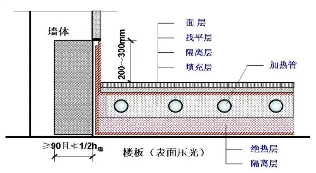
Waterproof structure of low-temperature radiant heated toilet
18. Indoor Staircase Handrail Heights
Handrails must be at least 0.90m high from the front edge of steps. For horizontal handrails near stairwells longer than 0.50m, the height must be at least 1.05m. In areas accessible to children—such as residential buildings, daycare centers, schools, cultural, commercial, sports, and landscape buildings—railings must prevent climbing. When vertical rods are used, spacing between rods should not exceed 0.11m.
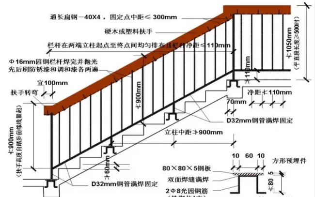
19. Stair Railing Installation
Railings and handrails must follow design requirements. If unspecified, stairways wider than 0.20m must have anti-climbing and anti-sliding features. Vertical rod railings must maintain rod spacing under 0.11m. Handrail heights should be at least 1.05m from the step front edge, increasing to 1.1m if the horizontal handrail exceeds 0.5m in length.
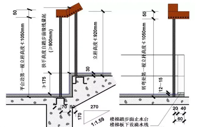
20. Protective Measures for Low Exterior Window Sills
When exterior window sills are less than 0.90m from floor, ground, or tread surfaces in residential buildings, protective measures must be installed. If design details are unclear, internal protective railings should be added. The gap between vertical railing elements must not exceed 0.11m, and the distance from the railing to the outer window frame should be between 0.1 and 0.2m. For buildings up to six floors, railing height must be at least 1.05m; for seven or more floors, at least 1.10m. Railings should be designed to prevent climbing by children.
21. Floor Drain Installation
Floor drains are required in areas with showers and washing machines, with a water seal depth of no less than 50mm. The floor slope for drainage must be at least 1%. Sanitary fixtures connected directly to drainage pipes without water traps must have a trap installed below the outlet, also with a minimum 50mm water seal. Drainage pipes in basements and semi-basements must not connect to upper drainage pipes.
22. Protective Railings at Open Spaces
Railings should be installed at balconies, external and internal corridors, connecting corridors, courtyards, accessible roofs, and outdoor stairs. No open spaces under 0.10m from floor or roof should be left. Set platform widths should not exceed 200mm; if wider, railing height should be measured from the tread surface.
23. Roof Drainage Requirements
The diameter of roof water outlets should be one size larger than the connected rainwater pipes. The drainage slope around outlets (diameter 500-800mm) must be between 5% and 10%. A 15-20mm wide groove should separate the outlet and leveling layer, sealed with waterproof material and covered with a waterproof membrane. For prefabricated houses, the groove depth must be at least 50mm.
24. EPS Board Installation Limits
Except at deformation joints, EPS boards pasted continuously on walls and floors should not exceed 12m in length or 20m in width. Otherwise, crack-resistant expansion joints 15-20mm wide filled with elastic closed-cell insulation and sealed with waterproof adhesive must be installed.
25. Gaps around Doors and Windows in Energy-saving Buildings
For general energy-saving buildings, leave a 20-30mm gap between outdoor door and window frames and wall openings (10-20mm for external window frames). Wider gaps are required based on exterior wall finishes: 40-50mm for brick facing, 50-60mm for metal curtain walls, and 70-80mm for stone curtain walls. These gaps must be filled with insulation materials, preferably polyurethane foam.
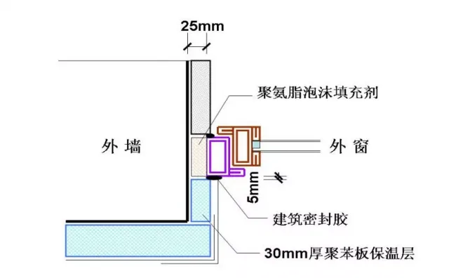
Construction structure of external window soft connection
26. Protective Layers for Exterior Wall Finishes
General elastic coatings, colored decorative mortar, and flexible brick finishes require a protective insulation layer consisting of one fabric and two layers of paste. For the first floor (EPS board density ≥ 22kg/m3), an additional layer of mesh fabric must be applied, forming a protective system of two fabrics and three pastes around exterior wall openings and areas with hard brick facades.
27. Reinforced Splicing for Composite Plastic Windows and Doors
Splicing materials for external composite plastic windows and connecting doors must include reinforced steel liners closely matching the inner cavity. Steel ends should extend 10-15mm beyond the splicing material, and both upper and lower ends must be firmly anchored to the structure.
28. Comprehensive Coverage of External Wall Insulation
The external wall insulation system must cover external door and window openings, parapets, balconies, footings, rain covers, canopy columns, balcony railings near walls, outdoor air-conditioning unit shelves, attached wall columns, protruding windows, upper floors, decorative lines, and partition walls near balconies, following design requirements. The insulation layer thickness must be at least 30mm.
29. Gaps and Expansion Joints for Auxiliary Works
Outdoor auxiliary works such as sprinklers, open ditches, steps, and ramps should have a 10-20mm gap from the building, filled with flexible sealing materials. Surface and base layers must comply with design and specifications. Longitudinal expansion joints for cement concrete dispersions should be installed with spacing no greater than 3m.
30. Construction of Deformation Joints
Construction methods and detailed structures for deformation joints on indoor and outdoor walls, floors, ceilings, and parapets must follow design requirements. If unspecified, current local standard design drawings should be strictly followed.


Must log in before commenting!
Sign Up