For guidance on using the stretch feature within a family, please refer to Constrained family geometry.
Solid or hollow stretching is the simplest type of geometry to create. You can sketch a two-dimensional profile of a shape on a work plane and then extrude it perpendicular to that plane.
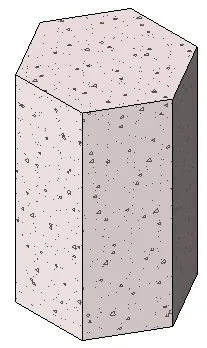
Example: Independent tension in a polygonal concrete foundation
Before extruding a shape, you can set its starting and ending points to control the depth. By default, the starting point is set to 0. The work plane is only used for sketching and for setting the extrusion direction; it does not have to be the start or end point of the stretch.
Below are typical steps for creating a solid or hollow stretch. These steps may vary depending on your specific design needs.
To create a solid or hollow stretch:
-
In the Family Editor, go to the Create tab, then to the Shape panel and do one of the following:
- If needed, set the work plane before drawing the stretch. Click the Create tab, choose the Work Plane panel, and select Settings.
- Click Stretch.
- For hollow shapes, click the Hollow Shape dropdown and select Hollow Stretch.
-
Use the drawing tools to sketch the extrusion profile:
- To create a single solid shape, draw a closed loop.
- To create multiple shapes, draw multiple non-intersecting closed loops.
On the Properties palette, you can adjust the stretch properties:
- To extrude from the default starting point (0), enter a positive or negative value for the Stretch End Point under the Constraints section. This value determines the depth of the stretch.
- After a stretch is created, the depth is not retained as a parameter. If you want to create several stretches with the same endpoint, draw the stretch shapes, select them, and then apply the endpoint.
- To stretch from a different starting point, enter a new value for Stretch Starting Point under Constraints.
- To set the visibility of the solid stretch, go to Graphics, click Edit under Visibility/Graphics Overrides, and adjust the visibility settings as needed.
- To assign a material by category, click the Materials field under Materials and Decorations, then select the desired material.
-
To assign the solid stretch to a subcategory, select the appropriate option under Subcategory in the Identification Data section.
Click Apply. - Click the Modify | Create Stretch tab, then select Complete Edit Mode in the Mode panel. Revit will finish the stretch and return you to the view where the stretch was created.
- To view the stretch, open the 3D view.
- To resize the extrusion in the 3D view, select the extrusion and use the grips to adjust its shape.


Must log in before commenting!
Sign Up