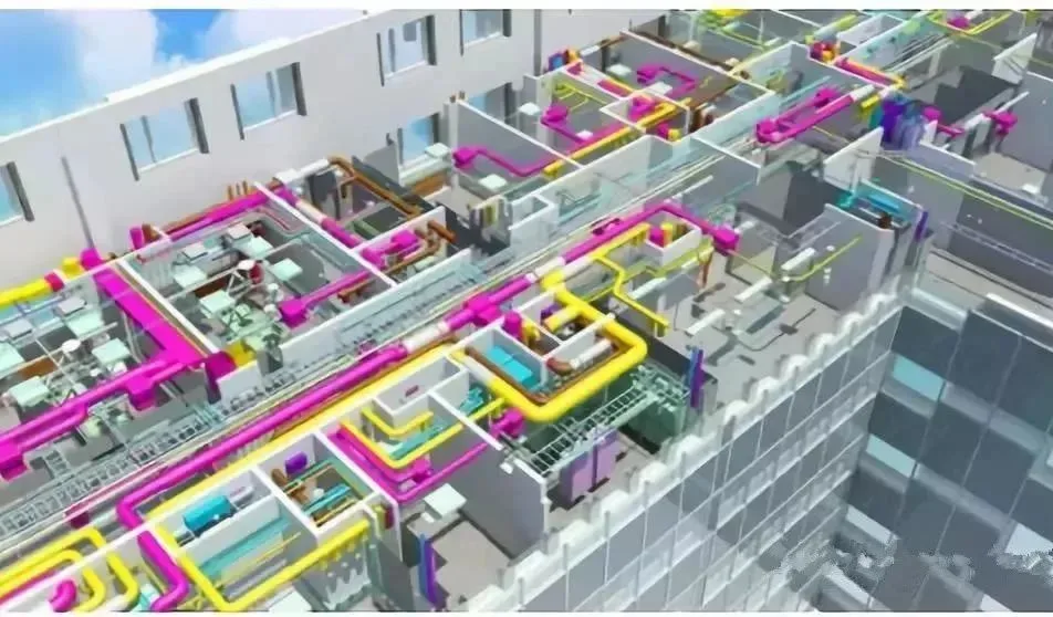
BIM technology follows the principles of building, drainage, and mechanical and electrical pipeline intersections, layout avoidance, and comprehensive pipeline planning, focusing primarily on roofs, floor corridors, ceilings, and basements. Special attention is given to equipment rooms such as water supply, fire pump rooms, and air conditioning rooms.
1. Principles of Pipeline Crossing Treatment
1. When drainage pipelines intersect with other pipelines during construction, the treatment methods must be approved by the property owner and relevant units.
2. In pipeline crossing treatments, maintain the minimum clearance distance wherever possible. Pressure pipelines should allow non-pressure pipes and branch pipes to avoid mainline pipes, and small-diameter pipes should avoid large-diameter pipes.
2. Methods for Pipeline Crossing Treatment
During the construction of drainage pipes, appropriate measures must be taken to ensure the safety and maintainability of lower pipes and prevent sinking or damage to upper pipes.
1. Concrete or reinforced concrete circular drainage pipes are placed at the bottom, with cast iron and steel pipes above. If the upper pipeline is already built, laying bricks and piers at the bottom of the trench supports the lower drainage pipe. When both upper and lower pipelines are constructed simultaneously, and if the steel or cast iron pipeline’s inner diameter is no more than 400mm, brick supports should be built on both sides of the concrete pipe.
2. For circular concrete or reinforced concrete drainage pipes (diameter <600mm) at the bottom, with cast iron and steel pipes on top, if elevation conflicts require lowering the drainage pipe, replace the lower pipe with double row cast iron pipes, reinforced pipes, or square ditches.
3. When a mixed structure or reinforced concrete rectangular pipe channel intersects with a steel or cast iron pipe above, and the clearance from the top plate to the pipe below is ≥ 70mm, brick piers can support the pipe on the side walls. If less than 70mm, fill the gap with low-strength cement mortar or fine aggregate concrete, ensuring the load does not exceed the top plate’s allowable bearing capacity. The support angle should be no less than 90°.
4. Circular or rectangular drainage pipes installed on top and cast iron/steel pipes below require sleeves or pipe galleries when constructed simultaneously.
5. When the drainage pipeline is on top and cast iron or steel pipes are at the bottom, and excavation to the trench bottom is difficult due to burial depth, the foundation of the upper drainage pipeline should be reinforced at the crossing point.
6. If a drainage pipeline intersects with a cable conduit block above, backfill the trench beneath the cable conduit foundation with low-strength concrete, lime soil, or bricks. When constructed simultaneously, lay a layer of medium or coarse sand on the backfill. If the conduit block is completed first, backfill with low-strength concrete without gaps.
7. When a drainage pipeline is installed at the bottom and another drainage or heat pipe trench is above, if both pipelines are built simultaneously (or if the upper is built first), increase the strength of the lower drainage pipe and fill the trench with bricks, C8 concrete, or sand.
8. If the drainage ditch is at the bottom and another drainage or thermal ditch is on top with elevation conflicts, simultaneously construct both pipelines, strengthen the upper pipeline’s foundation, and flatten the top plate of the bottom drainage ditch without reducing the discharge section.
9. When a prestressed concrete pipe conflicts with an existing thermal pipe trench and must pass beneath it, use steel pipes or reinforced concrete sleeves to pass through the thermal trench first, then replace prestressed concrete pipes with steel pipes.
10. Prestressed concrete pipes are placed on top, with other pipes below. If the upper pipes are built first, support piers are generally constructed at the groove bottom or square ditch cover plate for the lower pipes.
3. Comprehensive Layout Planning of Pipelines in Mechanical and Electrical Installation Engineering
General Provisions:
1. Large pipes take priority; small pipes must yield to large pipes.
2. Pressure pipes should replace non-pressure pipes where possible.
3. Low-pressure pipes should avoid high-pressure pipes.
4. Room temperature pipes may coexist with high and low temperature pipes.
5. Replace bendable pipelines with non-bendable ones; branch pipelines should yield to main pipelines.
6. Pipelines with fewer attachments should avoid those with more attachments.
7. Electrical pipelines should avoid heat and water; electrical circuits must not be arranged above hot water, steam pipelines, or directly below water pipes.
8. Maintain at least 500mm installation and maintenance space.
9. Reserve disassembly space for equipment such as cabinet machines and fan coil units in pipe galleries.
10. Reserve 250mm of decoration space above ceiling elevation in pipe galleries.
11. Avoid laying pipelines within 400mm outside the rental line; use this space for maintenance.
12. Reserve space for a rolling shutter door near the atrium in pipe galleries.
13. Reserve pipeline passage space above rolling shutter doors in each fire compartment; detour if space is insufficient.
14. During early layout adjustments, the owner must confirm the scope of comprehensive supports jointly with decoration, clearly defining commercial costs.
15. Clarify beam penetration scope during initial drawing adjustments.
16. To save costs, smoke exhaust systems with surplus pressure and infrequent use should have at least three water pipes for smoke exhaust and upward flipping air ducts.
17. Per Wanda’s control requirements, air conditioning water systems should avoid areas with suspended ceilings in public zones to prevent maintenance, leakage, condensation issues, and decoration conflicts from pressure testing.
18. For aesthetics in areas without suspended ceilings, fire protection, sprinkler, air conditioning water, conventional water supply and drainage pipelines should be laid together; whether a comprehensive bracket is made depends on prior business conditions.
19. To ensure aesthetics and minimize water damage, pipelines with bends should be bent over the entire span. For continuous bends, coordination with owners is advised to consider beam crossing; beam sockets can help resolve collisions.
BIM units must consider installation space for valves, brackets, insulation, etc., based on design drawings.
21. Generally, pipelines should not exceed two layers.
22. Pipeline Avoidance Principle: In order of priority, allow pressure to pass; small pipes avoid large pipes; simple pipelines avoid complex ones; condensation pipelines avoid others; pipelines with fewer accessories avoid those with more; branch pipelines avoid main pipes; non-insulated pipelines yield to insulated; low-pressure pipes avoid high-pressure; metal pipes yield to non-metal pipes; pipelines with easier maintenance are preferred.
23. Vertical pipeline layout principles: gas above and liquid below; insulation above, non-insulation below; high pressure above, low pressure below; metal pipes above, non-metal below; infrequent maintenance above, frequent below; electrical pipelines above water pipelines.
24. Installation and maintenance of pipes and shafts must coordinate fully with the building design; valve operation space should not interfere with building functions.
Detailed Rules for Mechanical and Electrical Disciplines:
① Water Supply and Drainage
1. Minimize pipeline bends.
2. Water supply pipelines are placed above drainage pipelines. Insulated pipes go on top; non-insulated below. Support small-diameter pipes above large ones or suspend them below.
3. Maintain a 15cm vertical clearance between cold and hot water pipes; horizontal height deviation should be within 5mm for bathroom faucets, relaxed to 1cm elsewhere.
4. Except for lifting pumps, non-pressure water pipes with slopes must maintain proper flow direction.
5. Horizontal clearance between water supply inlet and drainage outlet pipes should be at least 1m. For parallel indoor pipes, minimum clearance is 0.5m; for crossing pipes, vertical clearance is at least 0.15m. Water supply pipes should be above drainage pipes; if below, use sleeves at least three times the drainage pipe diameter.
6. Install spray pipes near the bottom, maintaining at least 100mm from the ceiling. In areas without ceilings, upward placement is preferable.
7. Lay professional water pipes in parallel with a maximum of two layers.
8. Gravity drainage pipes (sewage, rainwater, wastewater) must not be inverted; other pipes should avoid crossing gravity pipelines.
9. When PP-R water pipes run parallel with metal pipes, maintain at least 100mm net clearance, with PP-R pipes positioned inside metal pipes.
10. Water pipes should be placed below cable trays when layered.
11. Avoid pipelines blocking doors and windows or passing above motor, distribution, or instrument panels.
12. Maintain a minimum 100mm distance between pipeline outer walls. Valves should not be installed in parallel; if necessary, stagger them with at least 200mm clearance.
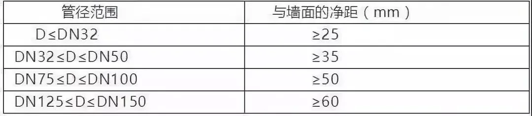
13. Pipeline spacing from walls or columns is detailed in the following table:
② HVAC
1. Ensure gravity slope for non-pressure pipes (usually condenser pipes), which should be placed at the bottom.
2. Air ducts and large busbar trays are generally installed at the top. Maintain at least 100mm clearance between air ducts and bridges.
3. Maintain at least 100mm clearance from prominent pipeline parts (outer wall, flange edges, insulation layers) to walls or columns.
4. The distance between the top of the air duct and the bottom of beams is usually 50-100mm.
If pipe gallery space is limited, flatten cross-sectional dimensions in consultation with designers to simplify elevation.
6. For multiple HVAC ducts, exhaust ducts should be higher than others; large air ducts higher than small ones. If two ducts intersect locally, they can be installed at the same elevation, with the smaller duct winding around the larger at intersections.
7. The horizontal main air conditioning pipe should be above the fan coil unit.
8. Consider condensate slope; ceiling installation height is typically determined by the condensate’s lowest point.
③ Electrical
1. Cable trays and bridges must be at least 2.2m above ground. Maintain at least 0.3m clearance between the top of cable trays and ceilings or obstacles.
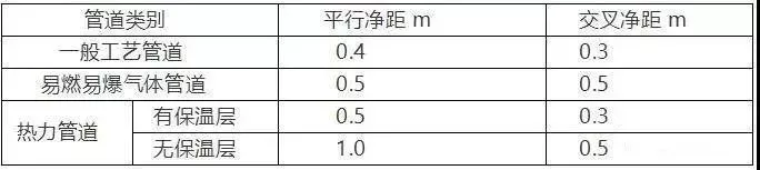
2. Cable trays should be installed below flammable/explosive gas and thermal pipelines. If no design requirements exist, minimum clearances are as follows:
3. When installed in ceilings, maintain an 80mm vertical clearance between groove covers and beams, and at least 100mm clearance from other trades.
4. Maintain at least 0.5m clearance between cable trays and electrical equipment.
5. When two cable trays run parallel at the same height, maintain at least 0.6m clearance between them and at least 100mm from walls or columns.
6. Inner bending radius of cable trays must be at least 0.3m.
7. For multi-layer cable trays, maintain clearances of at least 0.2m between control cables, 0.3m between power cables, and 0.5m between weak and power cables. Shielding covers can reduce this to 0.3m. The distance between the top of the tray and the ceiling or obstacles should be at least 0.3m.
8. Avoid installing cable trays above corrosive gas or thermal pipelines, or below corrosive liquid pipelines.
9. Maintain at least 300mm horizontal and vertical clearance between communication bridges and other bridges to prevent magnetic interference.
10. When changing elevation of bridges, use gentle slopes; avoid vertical flips. Maintain at least 100mm parallel clearance between bridges and other pipelines.
11. Cable trays should avoid stairwells, air conditioning rooms, pipe shafts, air ducts, etc.; detour when necessary.
12. Strong current bridges should be near distribution rooms and placed above weak current bridges if installed vertically.
BIM Subcontracting Unit Control Requirements
1. During construction drawing review, architectural modeling should be completed within one week after layout issuance and must match general drawings.
2. Within 15 days of receiving owner-approved drawings below ±0.00, provide comprehensive pipeline support, masonry hole, and structural column diagrams; within 20 days, submit comprehensive garage pipeline diagrams for review.
3. Complete air conditioning host room modeling and submit for review within 7 days after general contractor instructions.
4. Complete board hole reservations within 10 days after layout approval; verify shaft and machine room operating space; submit basic location maps within 15 days.
5. Within 7 days after instructions, complete comprehensive support diagrams (including main pipelines and fan coil units) in public areas; submit comprehensive pipeline and masonry hole plans within 12 days; position return air inlets and maintenance ports within 15 days for review.
6. Cinema sections should complete comprehensive support drawings within 5 days of instructions; submit comprehensive pipeline and masonry hole plans within 10 days for review.
7. Roof pipeline equipment foundation drawings should be completed within 10 days after instructions; submit comprehensive pipeline and masonry hole drawings within 15 days for review.
8. Complete structural column positioning diagrams within 3 days of instructions; masonry hole reservations within 5 days; submit comprehensive pipeline diagrams within 10 days for review.
9. Models should reflect decorative ceilings, pipeline valves, and comprehensive supports in public areas.
10. Small municipal administration tasks, including pipelines, landscapes, signage, and retaining walls, should be completed within 20 days after instructions.
11. BIM units must be capable of adjusting pipe diameters and detailed drawings, not just routing.
12. BIM units should produce professionally labeled and covered drawings, archiving each image properly.
Requirements for Effective Comprehensive Pipeline Layout Planning
1. While meeting design and functional requirements, pipelines should be concealed as much as possible within pipeline wells, electrical wells, pipe galleries, and suspended ceilings. Pipes should be laid along walls, beams, and columns in orderly rows and layers to avoid clutter, ensure clear layering, proper direction, and neat intersection handling for aesthetically pleasing installation.
2. Using shared supports and hangers with standardized spacing reduces project costs.
3. Construction management must have a clear overview of the project, especially subcontractors, to strictly follow unified detailed layout drawings and node diagrams, ensuring proper process organization.
4. Full coordination with structural and decoration engineering is crucial to ensure timely and accurate reservation and embedding, preventing rework and incompatibility issues.
The focus of pipeline comprehensive planning lies on roofs, floor corridors, ceilings, and basements. Key layout planning includes equipment rooms (water supply, fire pump, air conditioning, transformer and distribution rooms, heat exchange stations), water supply and drainage wells, pipe galleries, suspended ceilings, bathrooms, equipment floors, strong and weak current wells, air conditioning wells, and other areas.
Why focus on the roof? Pipelines for water supply, air conditioning, fire protection, and others are arranged on the roof to save indoor space. Many designs place pipelines and equipment on roofs. Therefore, roof pipeline layout requires coordination with civil engineering to ensure pipeline support heights meet roof waterproofing flood height requirements. Roof equipment foundations should be constructed alongside structural layers to guarantee stability and flood height compliance.
The corridor ceiling is the most concentrated pipeline layout area. Comprehensive layout here involves determining elevations and positions for each pipeline system to allocate reasonable space and establish construction sequences for various disciplines, enabling coordinated cross-construction.
Standardization of Drawing Production
Before discussing drawing production, it is important to clarify which drawings to produce and their purposes. Drawings are the design institute’s products and vary based on intent: conceptual drawings, working white drawings, comprehensive schematics, construction drawings, etc. The fundamental purpose is to reflect design intent, but expression styles and emphasis differ depending on the object represented.
In domestic architectural design, the bulk of work involves “construction drawings” stamped for construction, commonly called “blueprints” by contractors. These are used for cost accounting, regulatory review, and construction guidance.
This discussion focuses on construction drawings that satisfy cost accounting and construction guidance. Cost accounting requires accurate component descriptions and quantity calculations, which BIM software facilitates through precise digital component definitions. For construction guidance, component positioning and labeling must be clear, conflict-free, and easily identifiable. BIM’s 3D capabilities effectively resolve positional conflicts; remaining challenges relate to surface representation methods.
Revit software offers a highly open platform. Except for system families restricted without APIs, users can customize most tags by creating “families.” Tagging for machines, ducts, vents, water pipes, etc., is achievable by creating tag families that comply with national or enterprise drawing standards.
When drafting frames, set scale and length, add labels, and adjust coefficients per standards. After adding text and labels, import shared parameters by selecting instances and drawings. Load these into the title bar and pre-modify project parameters.
11 Principles for Comprehensive Layout of Electromechanical Pipelines
1. Why perform comprehensive layout of mechanical and electrical pipelines?
1. To optimize pipeline placement within buildings, minimizing occupied space and increasing ceiling height.
2. To anticipate and resolve construction conflicts in design, avoiding pipeline intersection and clashes on plans and elevations, ensuring smooth construction and reducing costs.
3. Well-organized pipelines facilitate maintenance and management post-construction. Each engineering discipline has process layout requirements; conflicts should be coordinated and resolved.
2. Preparation for Two-Dimensional Layout
1. Familiarize yourself with various professional drawings beyond your own discipline.
2. Process base maps by assigning architectural specialties to color 8, layering, and separating each discipline by nature.
3. Overlay various professional drawings onto the architectural base map.
4. Complete elevation requirements for each professional pipeline.
5. Draw sectional views as needed.
6. Separate completed professional drawings into distinct files.
3. Specific Layout Principles
1. Pipeline integration focuses mainly on HVAC, supplemented by water and electricity. HVAC ducts are largest; conflicts between water, heating, and electricity are resolved by the project manager, with a dedicated person finalizing the comprehensive pipeline drawing.
2. When multiple HVAC ducts exist, exhaust ducts should be higher than others; large ducts higher than small ones. Local intersections allow installation at the same elevation, with smaller ducts winding around larger ones.
3. Water pressure pipes should surround non-pressure pipes.
4. Air conditioning horizontal main pipes should be above fan coil units.
5. Consider condensate slopes; ceiling installation height is usually determined by the lowest condensate point.
6. Electrical cable trays are flexible and can be inserted as needed. Arrange air conditioning and drainage pipes first, then consider cable tray space. Avoid installing cable trays directly below water pipes.
7. Due to many water supply and drainage pipes, if possible, allocate separate horizontal space and avoid parallel runs with air conditioning pipes. When difficult, allow some water pipes to pass through beams. If beams interfere with suspended ceilings, switch to vertical water pipe systems.
8. Replace fresh air branch pipes that conflict with beams or pipes with flexible air ducts to avoid obstacles.
9. Leave some operating space in corridor ceilings for future maintenance; do not fill ceilings completely.
10. Complex projects require on-site comprehensive coordination, as drawings alone cannot fully clarify issues.
11. Consider installation space for small bridges, busbars, and sprinklers at the top and air ducts and water pipes at the bottom in public corridors. If conflicts arise, replace electrical and water pipes with ventilation pipes or water pipes accordingly.
Content source: Internet
This article is intended solely for industry learning and exchange. Copyright belongs to the original platform and author. For any infringement, please contact us for removal.


Must log in before commenting!
Sign Up