Drawing surfaces in SolidWorks is easier than many people think. By mastering the key features of basic commands and following a logical sequence, you can efficiently create complex surfaces. It’s important to note that many surfaces can be generated using solid commands, as demonstrated below.
Here is the step-by-step drawing process:

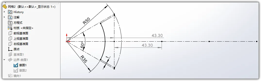
Start by creating a sketch on the top view plane. The gray dimension (43.30) helps position the rear array axis. Note the two short diagonal lines spaced 1 unit apart.
Next, create a new reference plane perpendicular to the top view plane, passing through the rightmost vertical line.
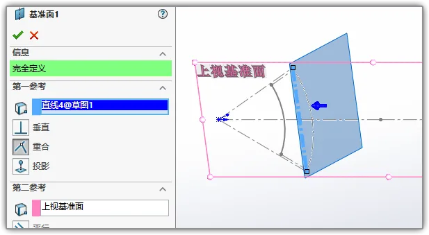
On this new plane, draw the arc as shown. Ensure the endpoints of the arc are vertically aligned with the inner equidistant line from Sketch 1.
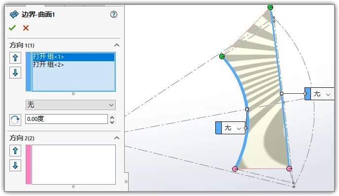
Use the Surface > Boundary Surface command to create a surface using the short arc from the first sketch and the arc drawn on the new plane.
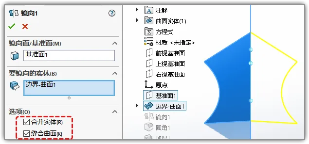
Mirror this surface, making sure to select the options for merging and stitching the surfaces.
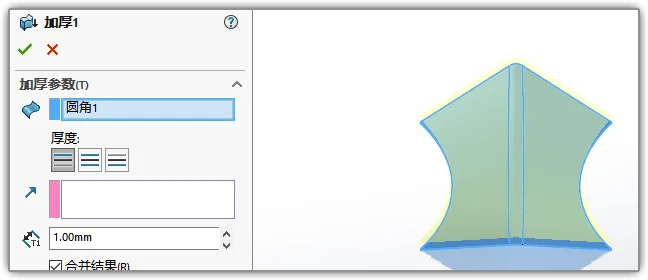
Next, round the corners and apply a thickness of 1mm to convert the surface into a solid body.
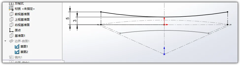
Now, sketch the front view. Draw three vertical lines to serve as the axes for the array. These lines should align with the points defined in Sketch 1.
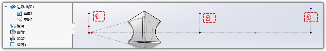
Use the array feature to replicate the surface multiple times along these axes, forming a patterned network. You can increase the number of instances to create a larger mesh.
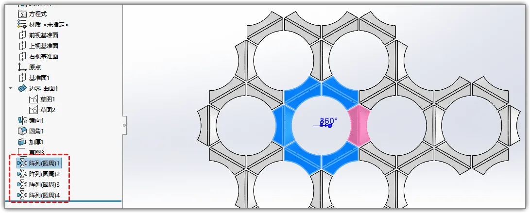
After just 30 seconds of rendering, you will achieve the result shown above!


Must log in before commenting!
Sign Up