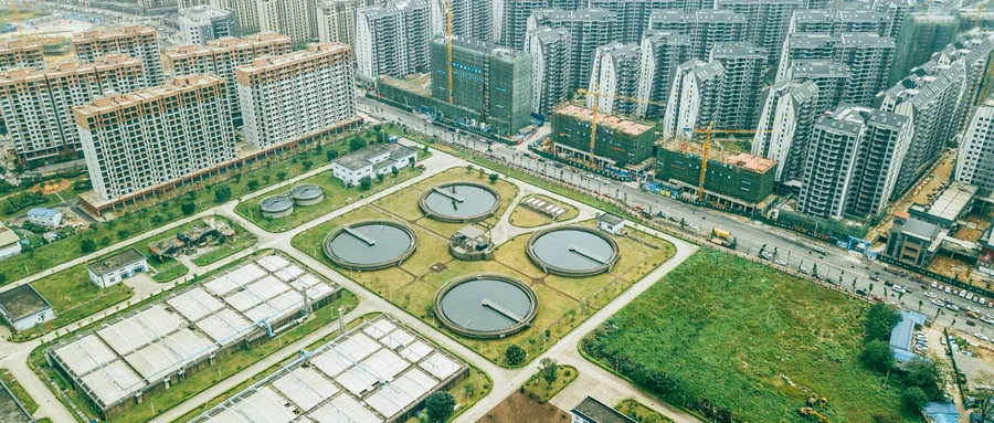
The sewage treatment project centers around water treatment facilities and involves several key construction aspects:
(1) The project is process-driven, with each stage corresponding to a single unit or a combination of multiple units. The entire process flow, from inlet to outlet, requires the coordinated operation of multiple structures, resulting in a variety of treatment types and quantities.
(2) Treatment structures such as grid rooms, aeration sedimentation tanks, and biological tanks feature complex and irregular shapes—including curved walls—that demand high precision during construction.
(3) Outdoor pipeline systems in sewage treatment plants consist of numerous types, including process pipes, sewage pipes, rainwater pipes, sludge pipes, and recycled water pipes. These pipelines vary in diameter and often intersect in three-dimensional space, making traditional CAD drawings—which represent nodes on vertical and horizontal planes—limited, cumbersome to review, and prone to errors.
(4) Additionally, precise coordination between pipelines and structural components is essential, with stringent requirements for holes, embedded parts, and other interface details.
These challenges significantly increase the complexity of constructing sewage treatment plants compared to conventional buildings. Currently, many plants suffer from design rework, low construction accuracy, poor engineering quality, and inefficient equipment operation. Such issues hinder the ability to handle increasingly complex water treatment demands caused by changes in capacity and processes. Therefore, adopting new technologies is crucial to optimize plant construction.
BIM technology has emerged as the ideal solution for enhancing the construction of processing plants due to its capabilities in visualization, coordination, optimization, modeling, and simulation. The application of BIM in sewage treatment plant design includes the following:
(1) Comprehensive site and road layout: Water supply and drainage engineers plan and arrange the site and road system based on plant zoning, sewage inflow direction, and process flow. The site model integrates buildings and structures within the plant area with the surrounding environment, while the road model incorporates traffic diversion strategies, enabling efficient and rapid finalization of the plant design.
(2) Integrated pipeline layout: Given the multitude of outdoor pipelines with large diameters that often intersect in complex ways, traditional 2D drawings fall short in representing pipeline integration. BIM pipeline models accurately detect real-time collisions at nodes and allow for immediate adjustments, resulting in a more rational and aesthetically pleasing layout. This approach reduces design changes during construction and provides a precise model that guides on-site work as well as future operation and maintenance.


Must log in before commenting!
Sign Up