This article is sourced from the WeChat official account: BimLearning.
Many users often find that Tekla lacks the section library they need and desire a parameterized form for easier modification later. This article will guide you through defining parameterized sections using the Section Editor.
Step 1: Download and Install the Sketch Solver Plugin
If you haven’t installed the Sketch Solver plugin yet, please do so now. If it’s already installed, you can skip this step.
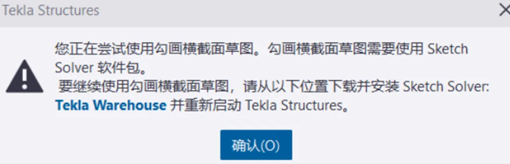
By default, Tekla does not include the Sketch Solver plugin. When you first attempt to define a cross-section in the Section Editor, you’ll see a prompt like this:
At this point, visit https://warehouse.tekla.com/#/landing, search for “Sketch Solver,” and click the download button:
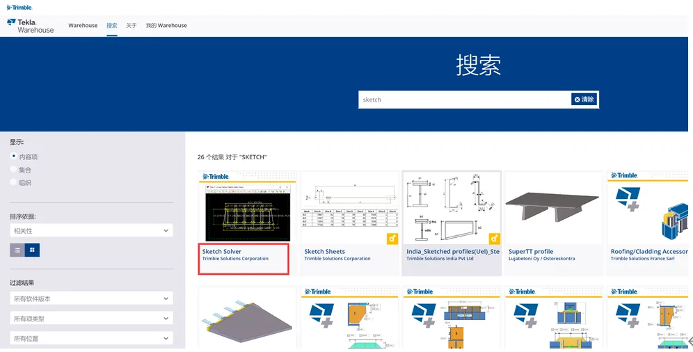
Note that downloading plugins from the Warehouse requires a registered Trimble ID. For guidance on registering, refer to Tekla account registration and activation of the education version.
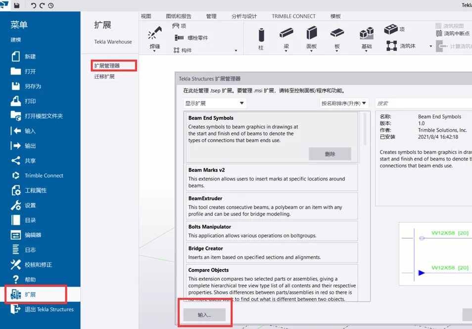
Install the Plugin
After downloading, extend the Sketch Solver plugin via Extension > Extension Manager > Input. The plugin won’t activate immediately—you must close Tekla and restart it to enable the plugin.
For detailed instructions, see How to download and install plugins from Warehouse.
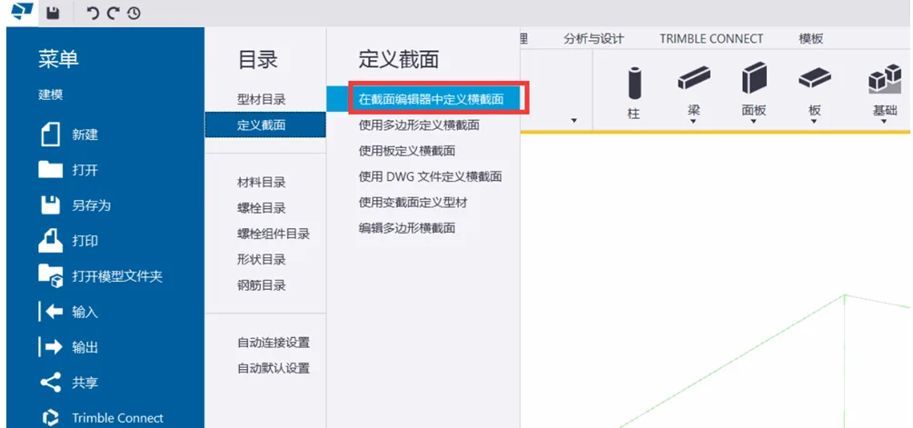
Step 2: Define Your Section Using the Section Editor
Navigate to the menu: Directory > Define Section > Define Section in Section Editor. This will open three panels in the view:
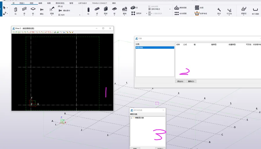
The panels serve the following purposes:
- Section Editor: Defines the shape of the section.
- Variables: Controls the parameters.
- 3D Graphic Browser: Helps quickly locate elements within the section editor.
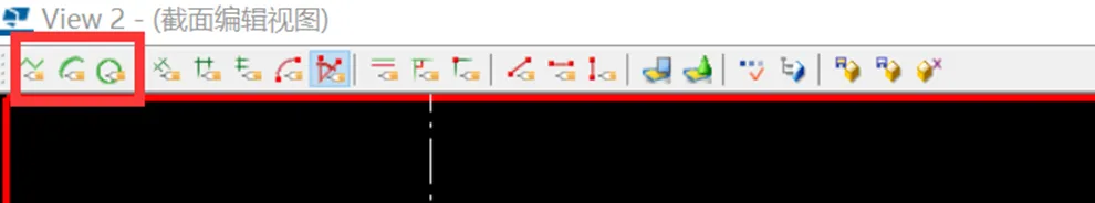
Section Editor Tools Overview
The first three tools in the Section Editor are used for drawing lines. Use these to create the desired shape.
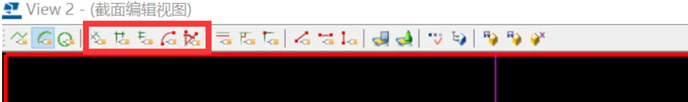
The fourth through eighth tools are for dimensioning your drawing.
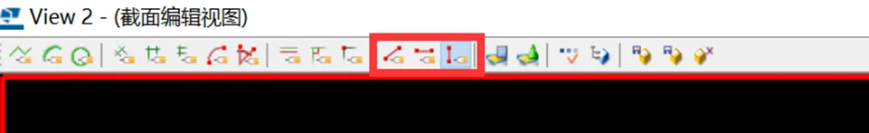
The ninth to fourteenth tools are used to apply constraints.
Variable Dialog Box Explained
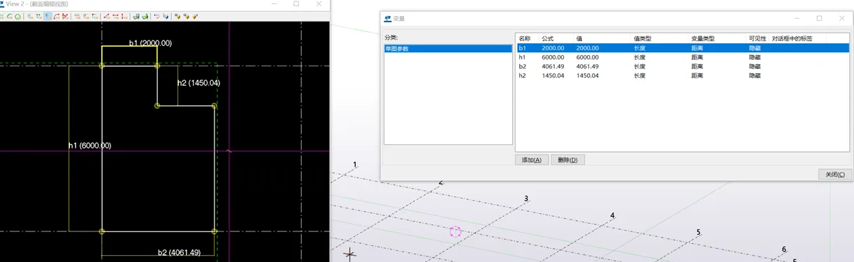
For example, when drawing a section with the polygon tool and applying horizontal/vertical dimension constraints, the corresponding values appear in the Variables panel, like this:
Here’s a close-up view:
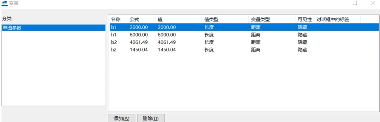
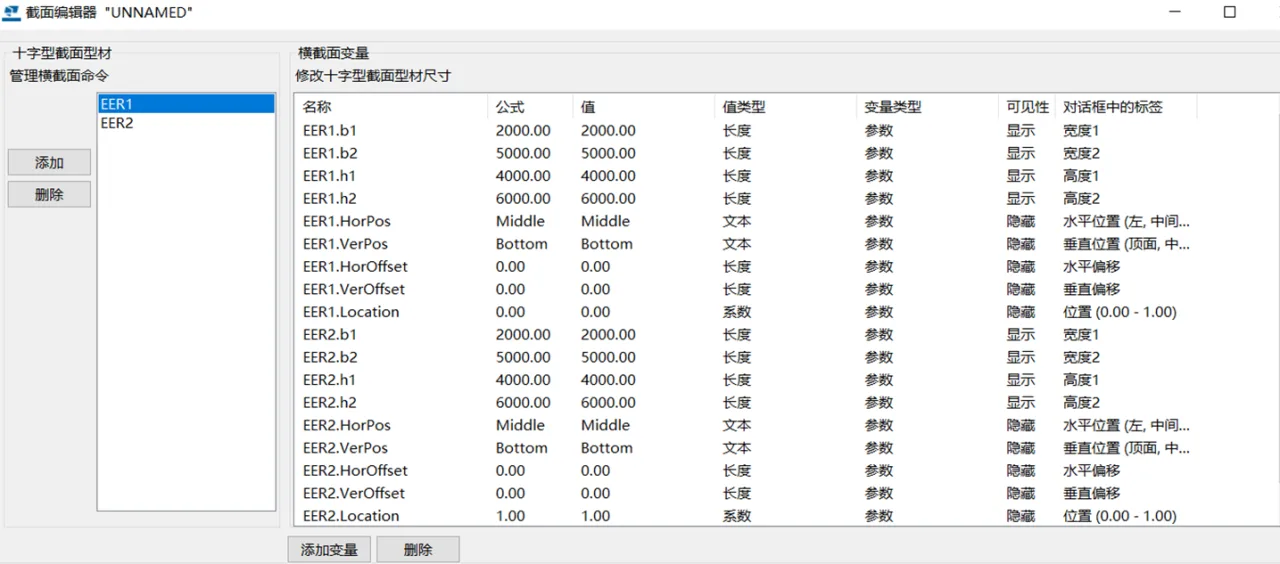
You can customize the variable’s name, formula, value type, variable type, and visibility. Visibility controls whether the parameter is shown and editable later in the section properties. If hidden, parameters cannot be modified. The label value corresponds to the attribute label in the section profile.
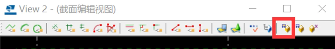
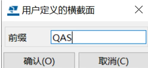
Once all parameters are set, click the Save button in the Section Editor and enter a name for your custom section.
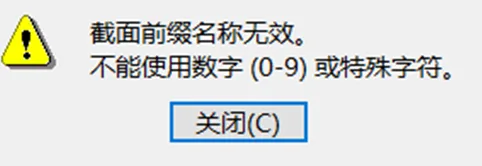
Important: The prefix for custom sections must be in English letters only. Numbers, symbols, or Chinese characters are not allowed and will cause errors like these:
Step 3: Use Your Defined Parameterized Section
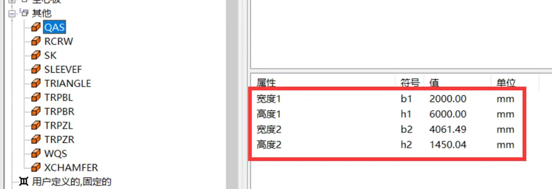
After creating your custom section, you can find it under Section > Section > Model – Other. You can then modify the parameter values to achieve different variations.
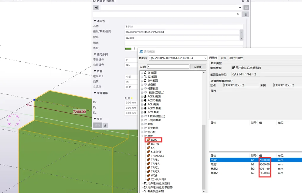
Extension: Define Variable Cross-Sections Using Parameterized Sections
If you need to parameterize variable cross-sections, you can define custom variable cross-section profiles using your parameterized sections. Here’s how:
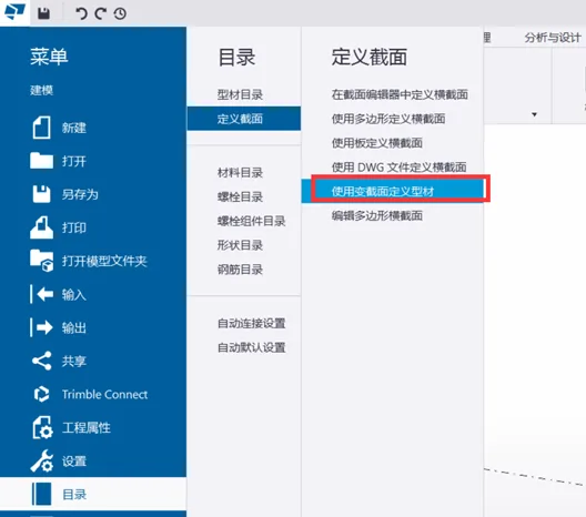
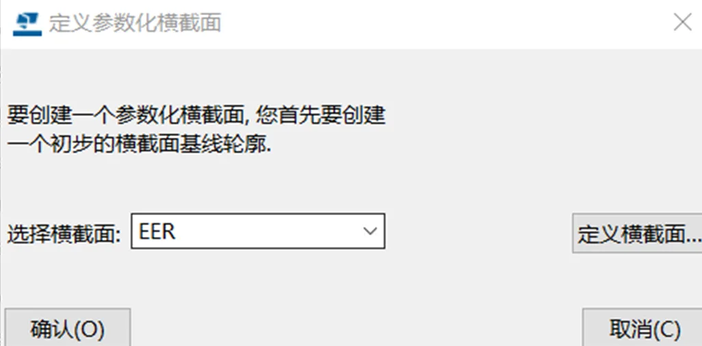
Go to Menu > Catalog > Define Section > Use Variable Section to Define Profile (after you have defined at least one parameterized section).
Select one of your parameterized base sections:
Enter the Section Editor and add another section (EER2 is added by default):
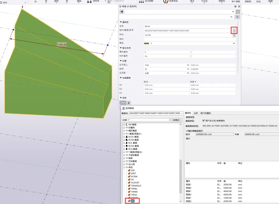
Save your changes with a prefix (again, only English letters allowed). After saving, locate the section with the new prefix in the section library to create a parameterized variable section.
Note: This article is shared for personal educational purposes only and not for commercial use. If there is any infringement, please contact us promptly. Due to limited knowledge, there may be errors—feel free to leave comments for corrections.


Must log in before commenting!
Sign Up