This article is from the WeChat official account: Meichuan Xinyifu, authored by Bear Boy.
Purpose
With the cabinets and countertops completed, it’s essential to create water blocking strips for the remaining sections. This task is a great example of how using dynamic components can speed up cabinet design, especially when aiming for efficiency.
1. Structural Analysis
Important Note: Although it seems simple at first, this task was overturned multiple times and turned out to be even more complex than designing a cabinet!
Initially, I assumed the water barrier was a long strip about 20mm thick and 45mm high. However, after sketching it out, I realized it wasn’t that straightforward. Comparing the physical water barriers on cabinets at home revealed its complexity.
The water barrier is a long strip featuring a rounded arc on one side, as shown below.
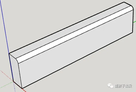
This design means the component has a specific orientation, with an arc of a particular size. This arc size needs to be dynamically adjustable, which could be challenging due to possible variations in thickness and height. Even if the arc size remains constant, there may be cases where thickness and height are fixed but the arc size changes.
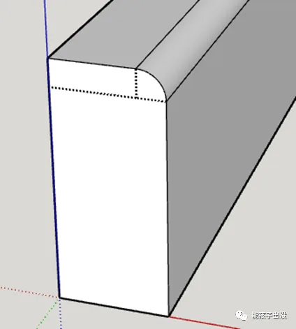
The initial approach divided the water barrier’s cross-section into three parts: two rectangles and a quarter-circle arc sector.
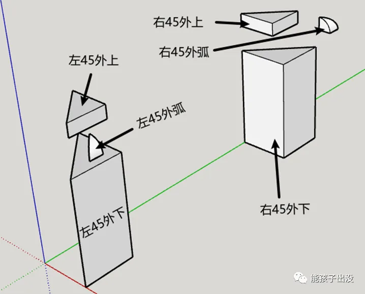
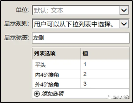
As Confucius said, solving one problem often leads to another. After addressing thickness, height, and curvature changes, a new issue emerged: not all water barriers have flat ends. There are three possible end shapes—flat, inward 45°, and outward 45° connections.
For flat ends, the previous division works fine. However, for inward and outward 45° connections, the division only accounted for one 45° angle, which doesn’t meet dynamic requirements.
After several attempts, the following modular combination was proposed:
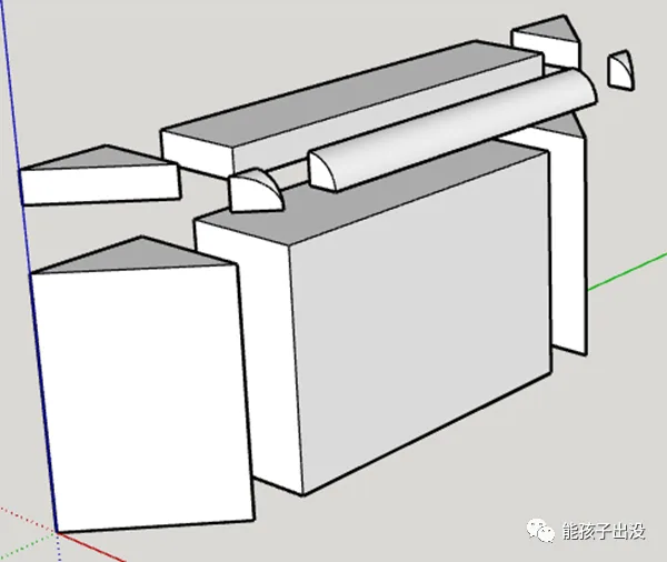
This example shows both ends internally connected at a 45° angle. Considering both ends could also be externally connected at 45°, an additional six modules were added, bringing the total to fifteen modules.
Note: The 45° angled ends were not combined through rotation and offset to reduce module count. Testing showed size deviations after multiple rotations, likely due to rounding errors during calculations. Therefore, separate modules were designed for each configuration, hiding unused ones as needed.
2. Production Process
2.1 Drawing the Modules
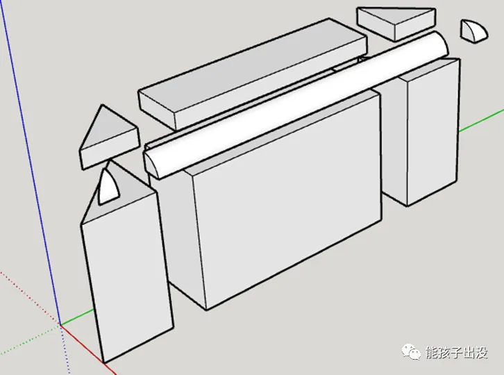
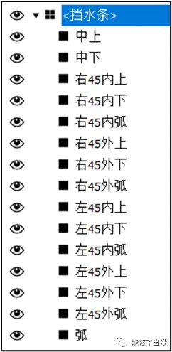
Based on the decomposition of the 45° angles at both ends shown below, draw each module separately and group them with the corresponding names:

Then add the external 45° angle module, grouping it accordingly:
The origin point of each module is the corner vertex closest to the 3-axis origin. If the position is off after drawing, you can adjust the origin using the coordinate axis tool.
Group all these modules under the name “Water Barrier”. Then convert them into components within this group.
2.2 Adding Attributes
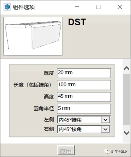
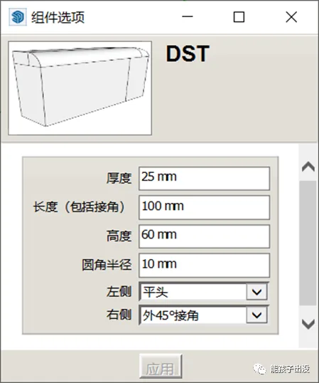
Next, add the following properties to the dynamic water barrier component:
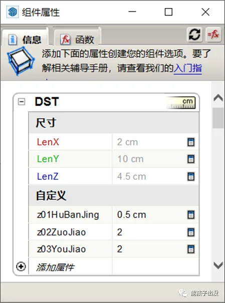

Refer to this diagram to configure the attributes:
Note: In this example, the component is renamed “DST” instead of the default “water blocking bar.” This avoids using parentheses in names, simplifying parameter references in functions. If Chinese characters appear in parameter references, they must be enclosed in parentheses to prevent errors.
2.3 Writing Functions
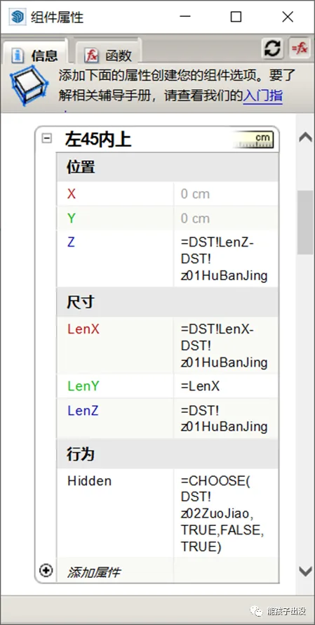
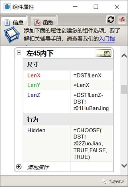
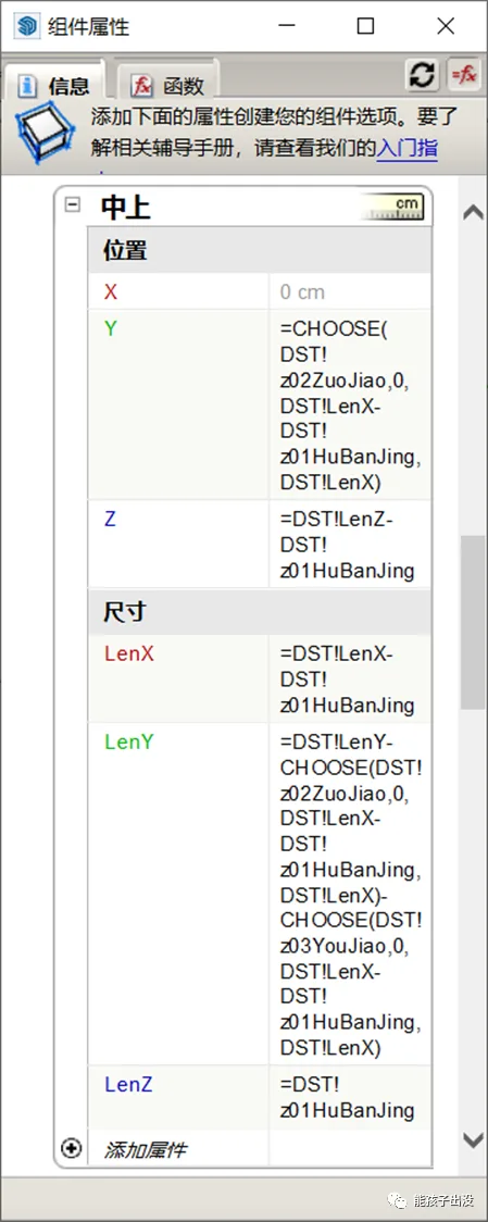
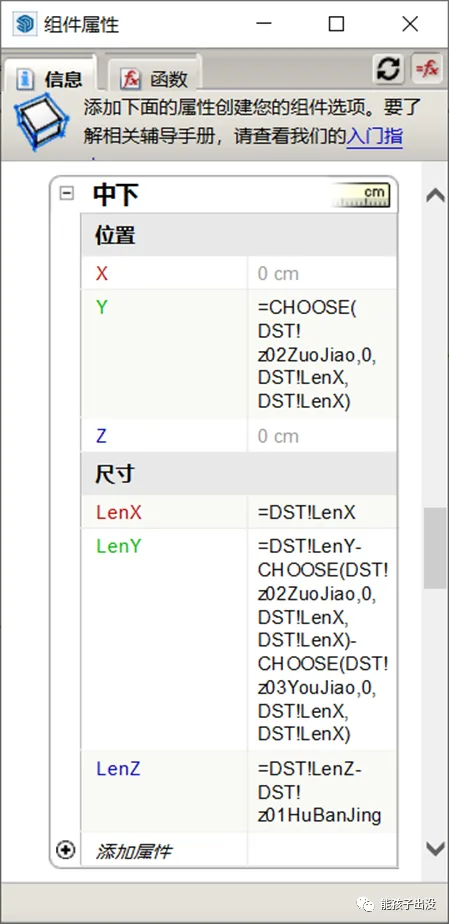
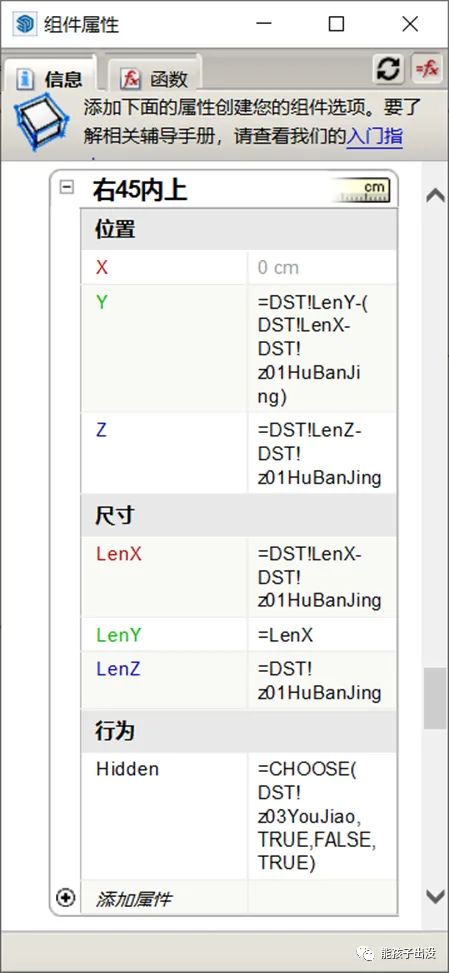
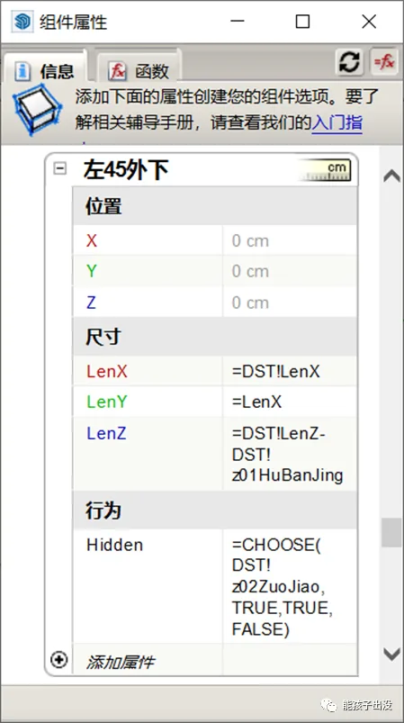
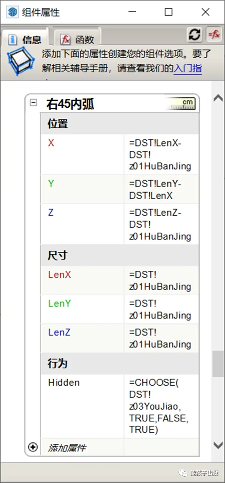
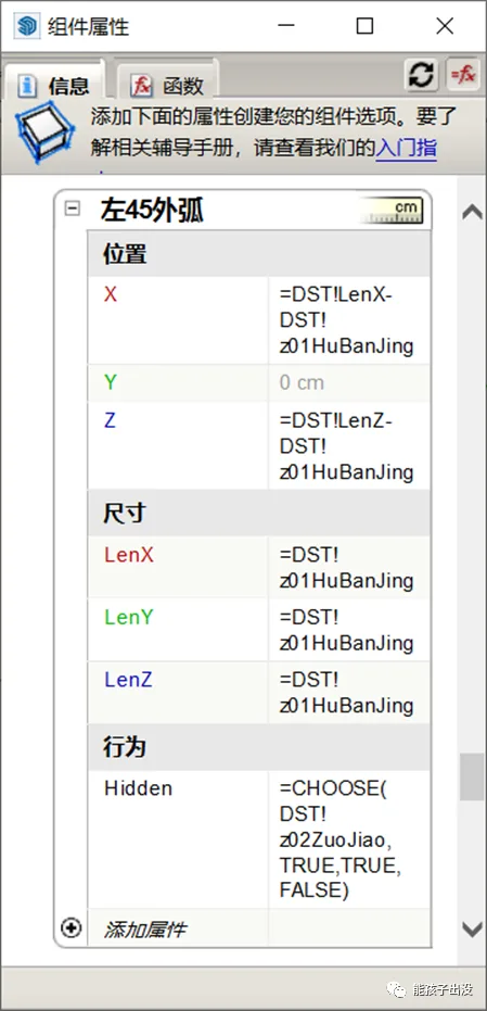
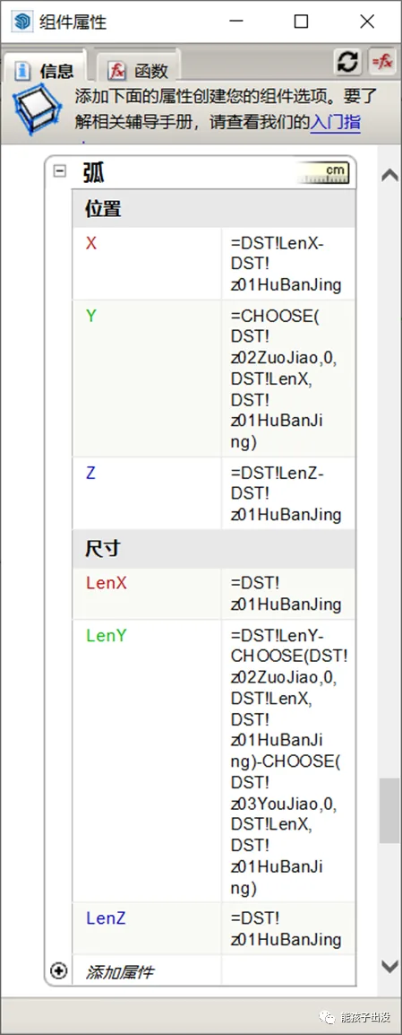
Assign attributes to each module and write functions as shown below:
Function Explanation:
- Set the position and length for each module’s appearance.
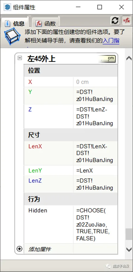
- Use the Hidden behavior function to control module visibility based on the current option. For example, the formula
=CHOOSE(DST!Z02ZuoJiao, TRUE, FALSE, TRUE)means that when the left end is set to “inner 45° joint angle,” the module is visible. - When the Hidden function returns FALSE, the module is shown; when TRUE, it is hidden.
- The CHOOSE function uses the first parameter’s return value as an index to select one of the subsequent parameters. In this case, DST!Z02ZuoJiao has three options: flat head (1), inner 45° joint (2), and outer 45° joint (3). Selecting “inner 45° joint” returns 2, so the CHOOSE function returns FALSE, making the module visible.
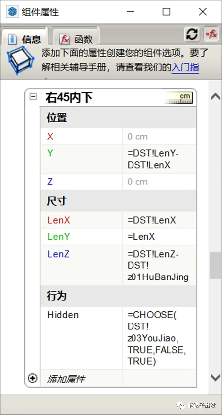
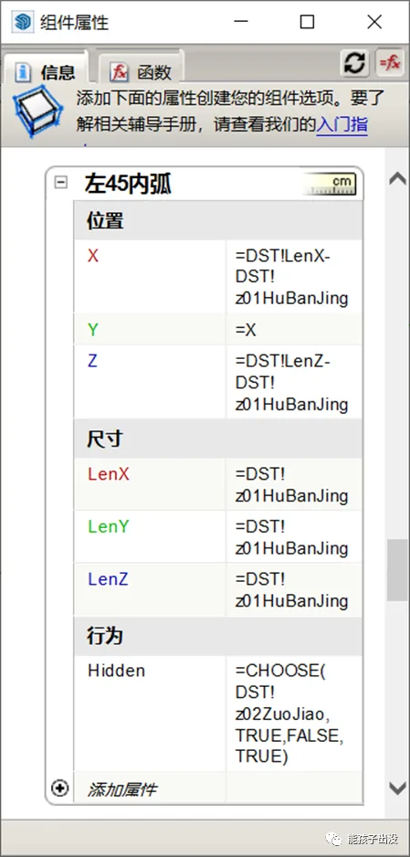
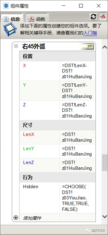
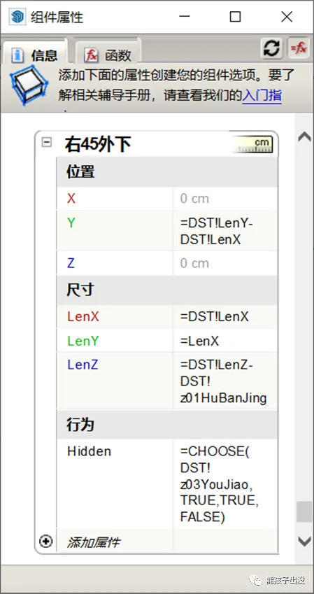
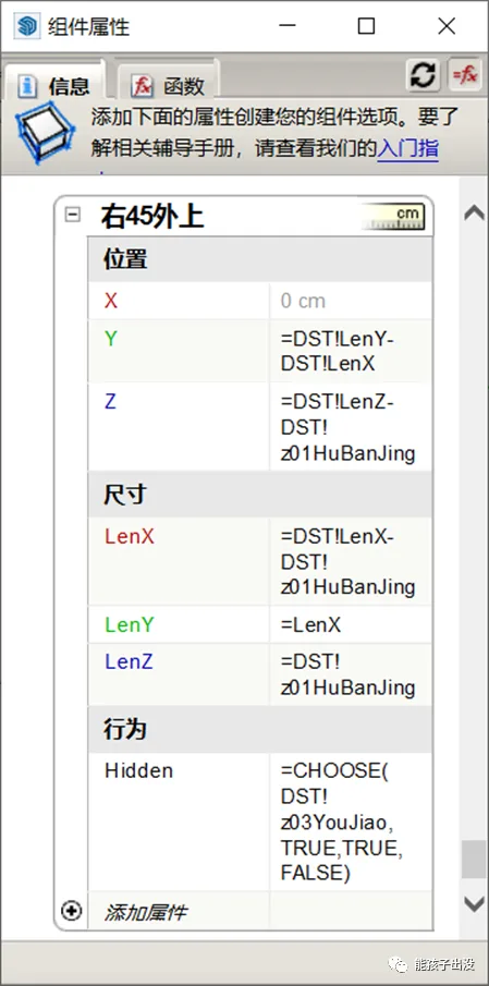
Functions for other modules are set similarly, as shown in the following diagrams:
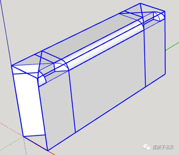
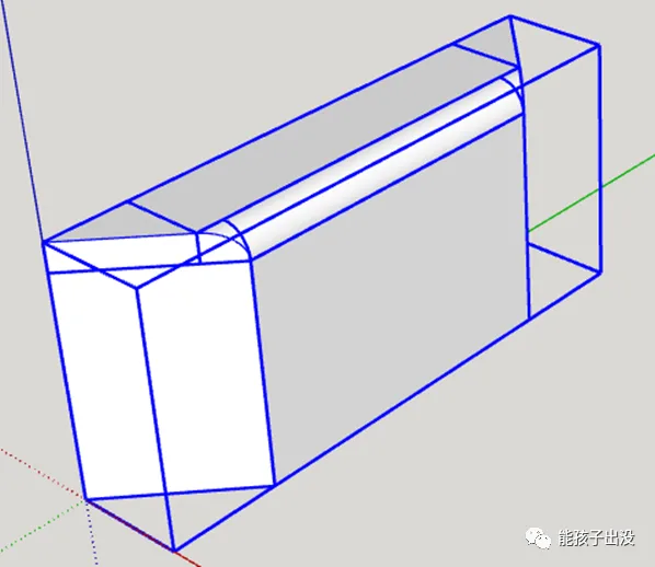
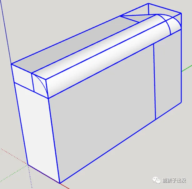
3. Final Results
Here are some examples of the finished water barrier components in action:


Must log in before commenting!
Sign Up