At the start of architectural design, the first crucial step is to establish the elevations and grids. These serve as reference points for defining the spatial relationships between various professional components or elements. In building projects designed with Revit, drawing the elevations and grids is essential because they provide the foundation for positioning building components in both elevation and plan views.
In the plan view, the axis grid acts as the centerline for wall placement. Meanwhile, in the elevation view, the elevation lines determine the wall heights. The precise positioning of windows, doors, balconies, and other components depends heavily on these grids and elevations. Essentially, elevations indicate the vertical placement of building elements, while grids represent their horizontal positioning on the plan.
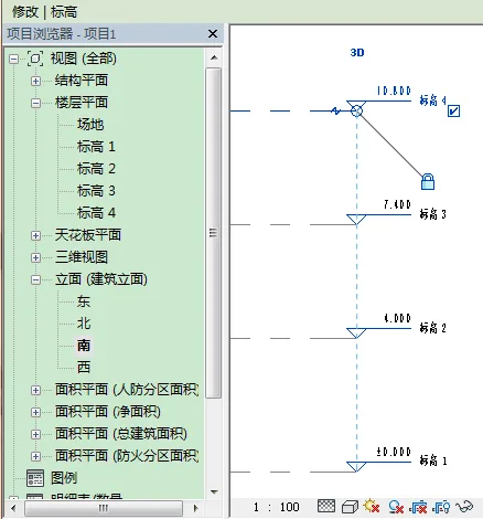
Figure 1: Elevation Creation
In practical design workflows, elevations are typically created first, followed by grids. An elevation consists of a series of parallel planes aligned along the vertical axis, including a header and elevation lines. The header displays both the elevation value and its name. When a level is created in Revit, the software automatically generates a corresponding floor plan named after that level, as shown in Figure 1.
The main methods to create elevations are:
- Draw Elevation: Use the elevation tool in the Building tab to draw elevation lines directly.
- Pick Elevation: Select existing elements within the elevation view to create levels.
- Array Elevation: Similar to the array command in CAD, this allows multiple elevations to be created simultaneously.
- Copy Elevation: Copy one or multiple elevations, functioning like the copy command in CAD.


Must log in before commenting!
Sign Up