This study focuses on the design of Xiangxue Station, the final station of Guangzhou Metro Line 6 Phase II. Located at the intersection of Kaichuang Avenue and Lihong Second Road, the station sits at center mileage YCK41+447. A single crossover line is positioned in front of the station, with a double storage line behind it. The station’s east end connects to an open cut access line, while the west end links to the Luogang Xiangxue shield tunnel section.
Xiangxue Station is an underground two-level island platform station, standing 10 meters tall. It features a fully open cut frame structure with two levels and two spans. The first underground level serves as the concourse, and the second level houses the platform. The station has an effective platform length of 120 meters and a total length of 381.2 meters. The outer width of the standard section is 19 meters, with a line spacing of 13 meters. The center rail surface of the platform is at an elevation of 8.97 meters according to Guangzhou City Construction standards. The station roof is covered by 3 meters of overlying soil, with an overall station height of 13.16 meters and an excavation depth around 16.36 meters.
The station’s main building area covers 15,224 square meters, while the total building area reaches 20,636 square meters. The main foundation pit’s earthwork volume is approximately 130,010 cubic meters, with ancillary structures requiring around 51,062 cubic meters of earthwork. Based on passenger flow analysis and surrounding planning combined with evacuation requirements, the station includes a total of seven entrances and exits, as illustrated in the floor plan below.
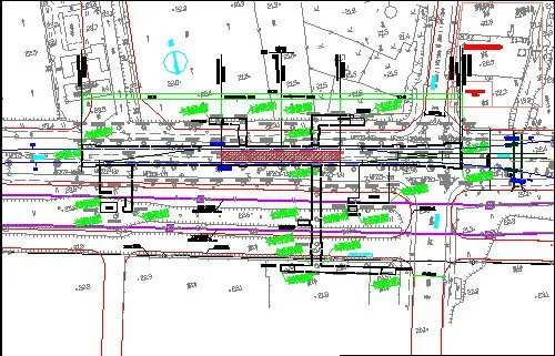
Figure 1: Station Floor Plan
Implementation of BIM Collaborative Design
2.1 Collaborative Design Patterns and Model Division
The project’s model creation primarily uses Autodesk’s Revit Architecture, Revit Structure, and Revit MEP software. Due to the complexity of multiple disciplines and interfaces—especially the intricate pipeline sections—collaboration cannot be effectively managed solely through Revit’s native worksets or linked collaborative design modes.
To address this, each discipline creates its own professional worksets from a central project file via the “Worksets” menu in Revit’s Collaboration tools. These worksets are saved to the local area network host, completing the central file setup. Each discipline then develops its models locally and integrates the design files of all disciplines into a comprehensive project model using the “Link Revit” function under the “Insert” menu, as shown in Figure 2.
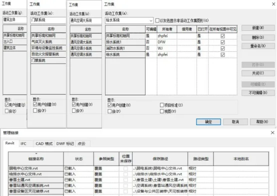
Figure 2: Collaborative Design Model Setup
The project employs a sub-model collaborative design approach to facilitate cooperation among disciplines and regions. Roles and personnel are assigned based on these divisions, with corresponding central files established for collaborative work within each profession and system. The model segmentation for this project is detailed in Table 1.
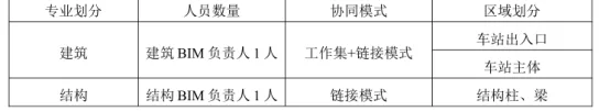
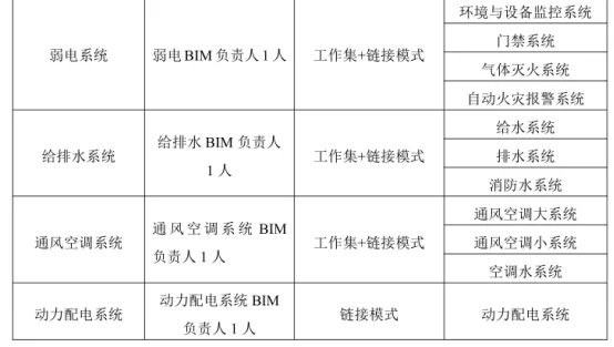
Table 1: Project Model Division
The project organization includes one project manager and one BIM manager, with each discipline having its own BIM manager. Responsibility for creating and applying regional division models is shared between model designers and application specialists within each discipline.
2.2 Collaborative Design Implementation Process
a. Planning and Preliminary Design
The planning and design scheme was completed based on requirements from relevant units. Although 3D models and related software were used for site analysis, passenger flow prediction, functional area division, and various evaluations, these are not detailed here. Model accuracy during the planning phase corresponds to LOD100, increasing to LOD200 during preliminary design.
The primary BIM task during preliminary design is gathering existing partial model information, assigning design tasks according to project progress, establishing an interaction platform, and enabling multidisciplinary collaboration.
Building on planning data, the architecture discipline leads the preliminary design. This phase focuses on the station’s overall layout, functional area division, and detailed building drawings. To finalize component dimensions, locations, and quantities, parametric families are created for components not directly drawable or missing from Revit’s family library.
The process begins by selecting a suitable template file for the required component properties, creating a blank project accordingly. Next, a family type is chosen based on the component category, usually using metric standard models. Components are then created within the blank model interface, with dimensions, materials, and parameters set to enable future reuse, as illustrated in Figure 3.
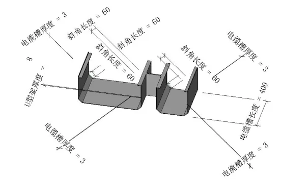
Figure 3: Parameterized Family Example (Cable Trays)
As the lead discipline in subway engineering projects, architecture model designers develop their models based on planning data and professional requirements using a working set collaborative approach. Other disciplines follow by designing their models through linking or working set collaboration based on architectural designs, as shown in Figure 4.
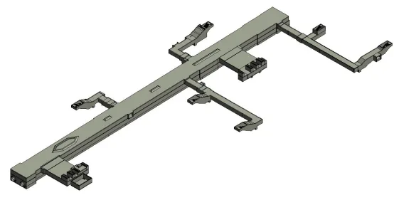
Figure 4: 3D Station Building Model
The project’s weak current system includes environmental and equipment monitoring, access control, gas fire extinguishing, and automatic fire alarm systems. Model designers collaborate primarily through working sets. Components typically include cable trays, rigid non-metallic conduits, junction boxes, fire extinguishing pipelines, and smoke detectors. These components are drawn from Revit’s built-in and custom family libraries. Pipe colors differentiate the systems, as illustrated in Figure 5.
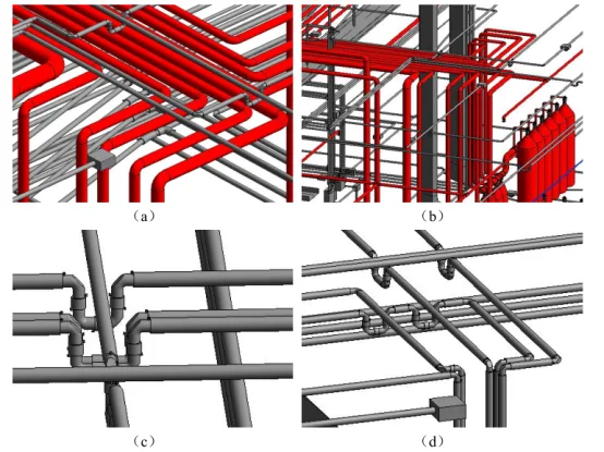
Figure 5: 3D Model of Weak Current Systems
The power distribution system is modeled using a linking approach, where professional models are created independently and then integrated through linking under a unified project origin, as shown in Figure 6.
Figure 6: Power Distribution System Model
The water supply, drainage, and fire water systems consist of three main subsystems: water supply, drainage, and fire water. Pipelines include inlet, outlet, fire water, and pressure pipes. Colors represent each system: yellow for water supply, gray for drainage, and red for fire water. Different model designers collaborate on these systems within the same workset, as depicted in Figure 7.
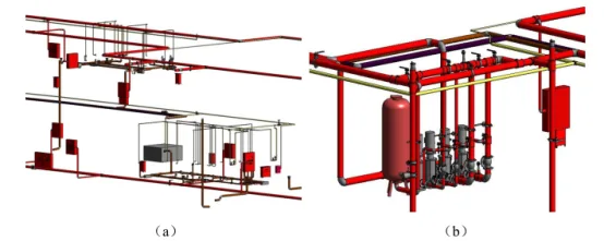
Figure 7: 3D Model of Water Supply and Drainage Systems
The ventilation and air conditioning system comprises three parts: large ventilation and air conditioning, small ventilation and air conditioning, and ventilation and air conditioning water systems. Pipelines include supply air ducts, return air ducts, and exhaust ducts. Three model designers work collaboratively within the same workspace, focusing on their respective system divisions, as shown in Figure 8.
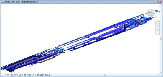
Figure 8: 3D Model of Ventilation and Air Conditioning Systems
Once the design models of all professional systems are completed, they are integrated. Model application engineers and BIM managers conduct clash detection, visual inspections, and checks for completeness and compliance. This process identifies and resolves errors, collisions, and design inconsistencies to improve the preliminary design, as illustrated in Figure 9.
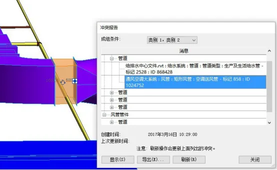
Figure 9: Clash Detection Results
During this stage, the collaborative design assistance system facilitates the submission of materials between disciplines or regions, eliminating the inefficiencies of manual, paper-based reviews. The system manages and archives data exchanges, preventing file misplacement or loss that can hinder dispute resolution. The workflow is outlined in Figure 10.
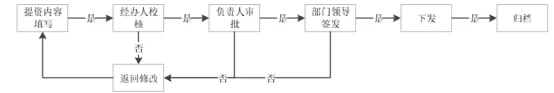
Figure 10: Workflow for Mutual Data Submission
When materials are submitted across different professional interfaces, submissions are first sent to the office for verification. If verification fails, materials are returned for revision. Once verified, they are countersigned and reviewed before submission to the professional responsible person for approval. If approval is denied, the process repeats until authorized. Finally, documents are signed by the department leader, issued, and archived.
Author: Dong Fuwen (Xi’an University of Technology)
For learning and communication purposes only. Copyright belongs to the original author. If there is any infringement, please contact us for removal.


Must log in before commenting!
Sign Up