Project Overview
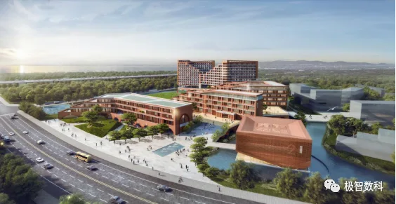
This project is situated on the north side of Haiyang Tianyuan in Bao’an District. Upon completion, it will add 3,000 student seats and 60 classrooms to Shenzhen. The site covers approximately 67,528 square meters, with a total built-up area of 110,000 square meters. This includes an underground construction area of 16,841 square meters and an above-ground area of 45,428 square meters. The foundation pit is 6 meters deep, the building reaches a total height of 54.5 meters, and it consists of one underground floor and 15 floors above ground.
As one of the key projects in Bao’an District, Shenzhen, this development has received several prestigious awards, including the Shenzhen Quality Engineering Award, Guangdong Province Quality Engineering Award, the BIM New Infrastructure Cup Second Prize, and the Installation Star Third Prize.
Key Challenges and Difficulties in BIM Implementation
Given the project’s significance and accolades, delivering a high-quality outcome was paramount. The project faced several critical challenges:
- Soft soil foundation combined with a tight construction schedule
- Indoor sports facilities with complex mechanical and electrical piping
- Tall formwork and comprehensive scaffolding requirements
- High-quality standards expected for key projects
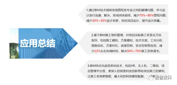
To address these challenges, the project leveraged BIM technology to improve construction efficiency, minimize changes and rework, simulate complex node processes, and enhance quality and safety management. An information-driven construction platform enabled precise and comprehensive dynamic control, which was essential to resolving project issues.
BIM Application Highlights
1. Soft Soil Foundation and Tight Schedule
The project is located near the seaside with challenging geological conditions, including silt layers up to 16 meters deep. The foundation pit excavation is deep, reaching 6 meters, making the excavation process complex.
BIM technology was instrumental in advancing 3D geological modeling, excavation planning, simulation of excavation operations, and visualizing construction progress.
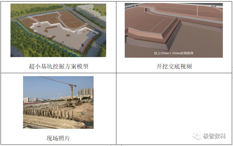
Excavation Planning Based on BIM
The foundation pit covers an area of 22,298 square meters with a depth of 6 meters. The soft, fluid soil creates difficulties such as uneven settlement and risks to adjacent structures.
Using Revit, the team modeled the foundation pit and surroundings to optimize the excavation plan. The excavation was divided into three layers, each with a maximum depth of 2 meters. During excavation, slopes were reinforced and soil replaced to ensure stability.
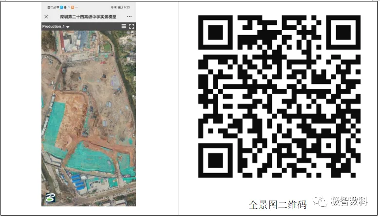
Drone-based Aerial Photography and Solid Modeling
Combining BIM technology with drone aerial photography allowed for real-time geographic data collection and site monitoring. This enabled effective construction progress control and timely plan adjustments to address on-site deviations and delays, keeping the project on track.
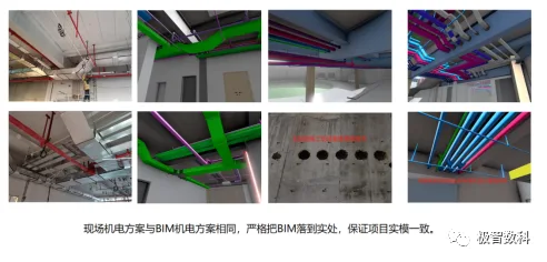
2. Indoor Sports Facility and Complex MEP Pipelines
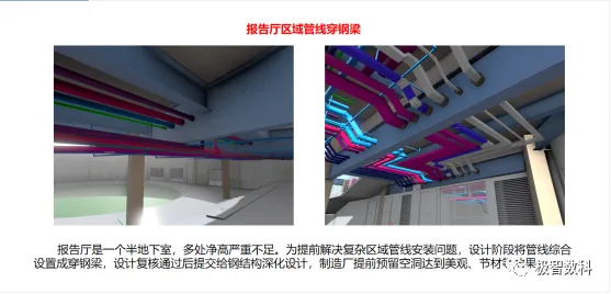
To maximize campus facilities within limited space, the basketball court and swimming pool were located in the basement. The required ceiling heights for indoor sports venues were achieved by utilizing the hollow structure between the basement and first floor. This arrangement caused multiple professional pipelines from the garage, basketball court, swimming pool, and auditorium to intersect and crowd the space.
BIM was key in modeling mechanical, electrical, and plumbing (MEP) pipelines, enabling 3D detailed design, coordinated layout, collision detection, and net height analysis to prevent future conflicts.
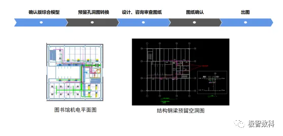
Structural Casing Reservation via BIM
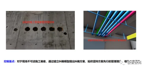
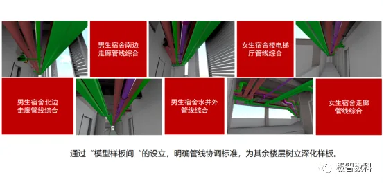
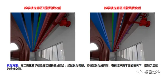
Comprehensive Pipeline Coordination
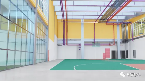
Net Height Management through BIM Walkthroughs
BIM walkthrough technology simulated the basketball court environment to analyze net heights, ensuring compliance with high-end decoration requirements and avoiding obstructions from curtain wall structures, thus preventing future issues.
Single Discipline MEP Pipeline Drawings via BIM
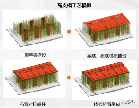
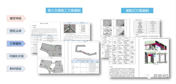
3. Tall Formwork and Full-scale Scaffolding
The dormitory building features a unique design with a local clear height of 9.8 meters on the second floor, making the installation of tall formwork a critical and challenging task with significant safety concerns.
BIM was used to create virtual scaffolding and formwork models, simulate installation, identify safety risks, and generate construction process videos for training on-site personnel. This ensured accurate information management and upheld safety and quality standards during construction.
High Formwork Planning through BIM
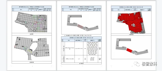
Construction Disclosure of High Formwork via BIM
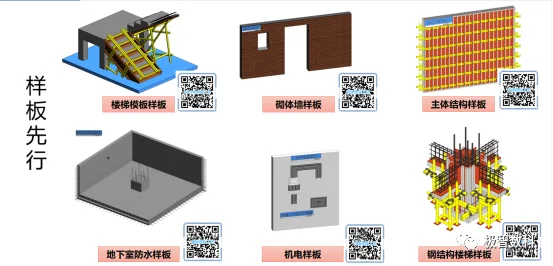
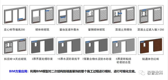
4. High-Quality Standards for Key Projects
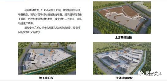
3D Site and Construction Interface Layout Using BIM
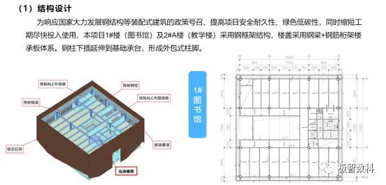
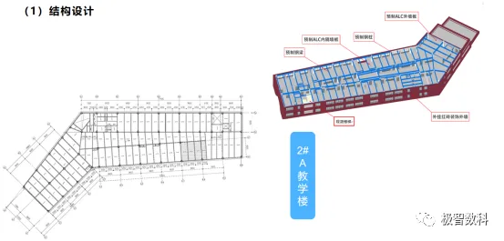
Prefabricated Structural Design Based on BIM
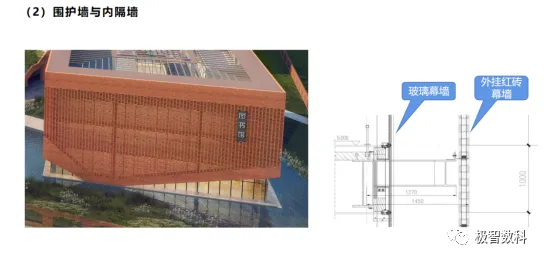
Detailed Curtain Wall Node Design with BIM
Traffic Route and Sunlight Analysis via BIM
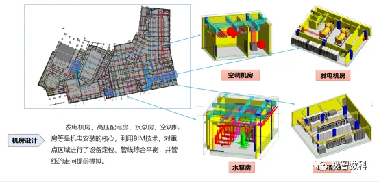
Prefabricated Computer Room Deepening Using BIM
MEP Pipeline Layout Planning Using BIM
Steel Beam Prefabrication and Opening Based on BIM
Construction Process Flow Visualization via BIM
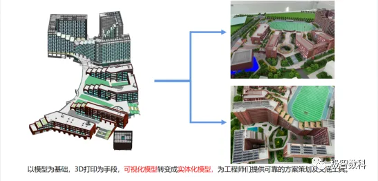
3D Printing Technology Integrated with BIM
Construction Planning Supported by BIM
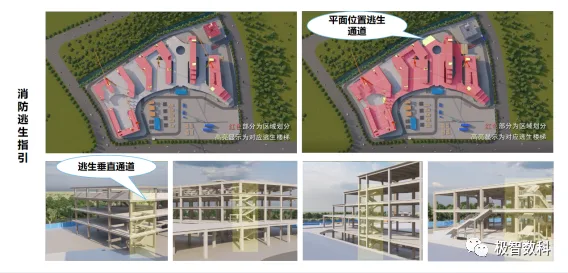
Risk Spatial Distribution and Fire Escape Guidance via BIM
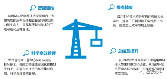
Project Implementation Summary


Must log in before commenting!
Sign Up