This article is sourced from the official account: Yuanhai Guangzhu.
This project comprises two separate buildings: a grand theater and a concert hall. Using the concert hall as an example, we will explore several applications of BIM technology for pipeline integration in public construction projects.
Project Overview
The concert hall features one basement level, four above-ground floors, and a roof level, reaching a total height of 23.3 meters. Its main functional spaces include a 1,000-seat concert hall, a multi-purpose hall, conference rooms, offices, and equipment rooms. The above-ground area covers 32,045.6 square meters.
BIM Application Analysis
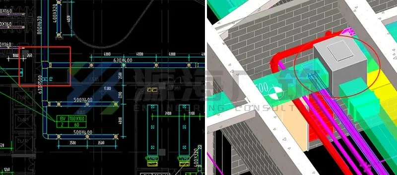
1. Evaluating Changes in Duct Size
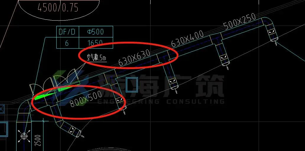
One of the most common challenges in public construction projects involves air duct sizing. While it’s possible to adjust duct dimensions with equal cross-sections, it’s crucial to assess whether such changes are reasonable. For example, in this case, the drawing shows an air duct size of 800×500, while the diameter is 630×630—indicating a decrease in width but an increase in height. Typically, the diameter of main duct sections decreases progressively, but since the cross-sectional area remains unchanged here, the diameter should not be altered.
Solution: The design team responded by adjusting the 630×630 air duct to 630×500.
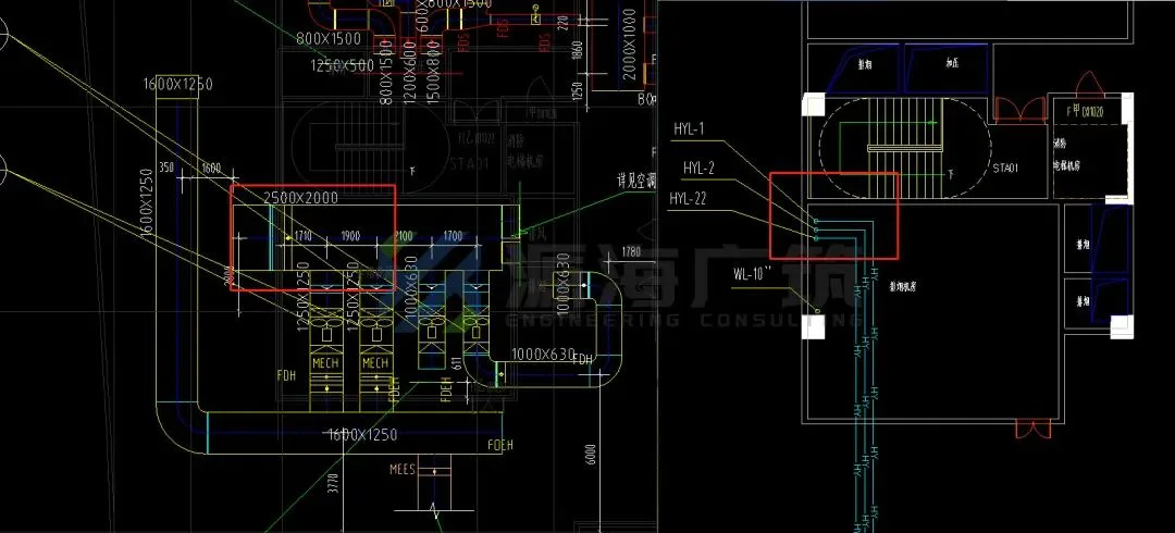
2. Changing the Air Duct Route
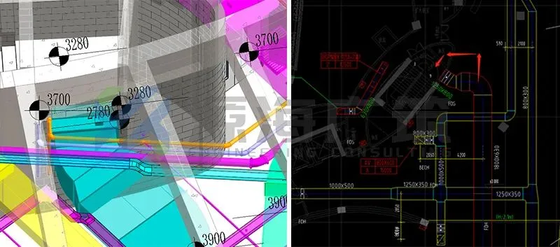
In this instance, a 125×800 air duct entering the stairwell collided with a double-layer beam. The upper beam’s bottom elevation is 3,700mm, the lower beam’s top elevation is 3,280mm, and its bottom elevation is 2,780mm. The large duct is located in the corridor, and when it bends below the beam, the net height drops below 2,000mm, significantly restricting corridor clearance. After thorough consideration, adjusting the duct route was recommended.
Solution: The design team proposed removing the partition wall between the basement staircase and the air shaft at the stairwell, relocating the duct outside the landing to connect with the basement staircase, as illustrated below.
3. Static Pressure Box Implementation
On the south side, the fresh air duct is adjacent to a rolling shutter door, while the east side of the north area is a corridor. Due to inconsistent net heights when elevating the duct, if the branch pipe passes through the rolling shutter door (as typically done), it requires raising the pipe and lowering the beam height on the right side. Such up-and-down bends negatively impact the appearance.
Solution: Use a static pressure box in place of a three-way valve, allowing the air duct to be laid out flat and improving aesthetic appeal.
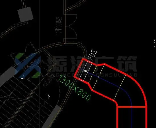
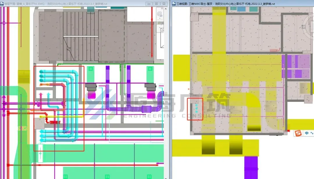
4. Roof Rainwater Pipe Positioning
According to the original design, there is a conflict between the siphon rainwater pipe and the smoke exhaust air pipe near the roof. The fan is a floor-standing model, leaving no space below for the rainwater pipe to pass.
Solution: Reroute the siphon rainwater pipe from a lower level, relocating the vertical pipe exit point on the roof to avoid interference with the smoke exhaust duct.
5. Relocating Condensate Discharge
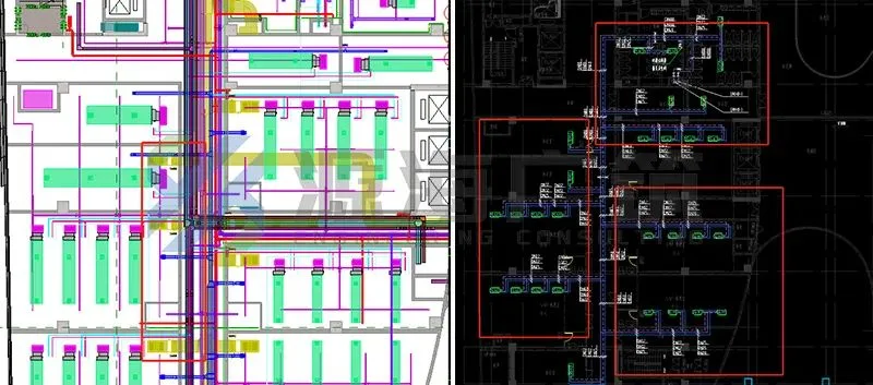
The condensate pipe cannot avoid intersecting with the smoke exhaust pipe based on the overall piping layout. Routing it separately under the smoke exhaust duct would reduce the net height in certain sections.
Solution: It is recommended to divide the condensate drainage into three zones, concentrating discharge into the nearest bathroom floor drain as shown in the diagram. This approach preserves net height and reduces material usage.
These are some practical BIM applications in public construction projects. Have you found these insights helpful?


Must log in before commenting!
Sign Up