Road design drawings are typically delivered in a standard A3 format (420mm × 297mm), with scales of either 1:1000 or 1:2000. Since a single drawing often cannot cover the entire road area, multiple drawings must be divided into sections. While basic CAD commands can create viewports to achieve this, the process becomes labor-intensive for long routes. Thankfully, Civil 3D’s Create View Frame command simplifies route plan framing.
1) Creating a Picture Frame
To begin, click the Create View Frame command located under the Output tab, as illustrated in Figure 1.

Figure 1: Create View Frame Command
In the pop-up Create View Frame dialog box, specify the route and station range. Then, proceed by clicking “Next” step-by-step. Set the drawing options to create only planes, align the drawings along the route direction, and insert match lines to assist in framing. This will complete the creation of the drawing frames, as shown in Figure 2.
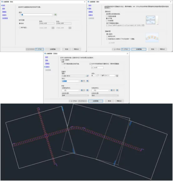
Figure 2: Creating a Map Frame Along the Route
2) Creating Drawings
Next, click the Create Drawing command. Set the drawing frame scope to “All,” enable the option to create all layouts within the current drawing frame, and specify the storage location for the drawing set. This process completes the creation of segmented road plan design drawings, as shown in Figure 3.
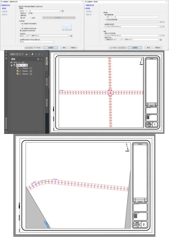
Figure 3: Creating a Plan Drawing Frame


Must log in before commenting!
Sign Up