By customizing the inspection set within the Civil 3D template file (.dwt), you can verify whether the key parameters of road horizontal and vertical designs comply with design specifications during route creation. The inspection targets for the route’s horizontal layout include straight lines, curves, transition curves, and tangent intersection points. For the longitudinal section, the inspected elements include straight lines and curves.
To begin, customize the inspection set by opening the Toolspace palette. Navigate to Settings > Route > Design Inspection. Right-click the graphic element you want to check, select New, and create a design check set for that specific element type, as shown in Figure 1.
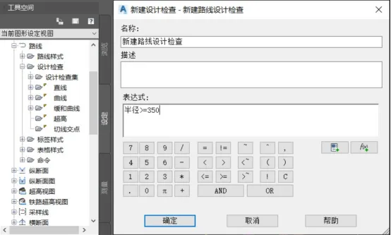
Figure 1: Creating a New Design Inspection
In the New Design Check dialog, name your check and click Insert Properties to add parameters such as radius into the Expression dialog. Use functions, constants, and logical operators to build your custom design check formula. Click OK to finalize the design check.
Next, select the route object you want to inspect, right-click its properties, and enable both Use Standard Based Design and Use Design Check Sets options, as illustrated in Figure 2.
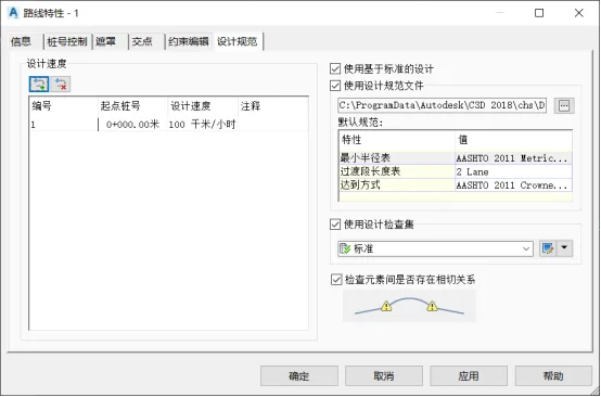
Figure 2: Enabling the Use of Inspection Sets
Then, click Edit Design Inspection Set. Within the Design Inspection Set dialog, select the curve type under the design inspection directory. Choose the newly created route design inspection set and add the surface inspection to it. Confirm by clicking OK, as shown in Figure 3.
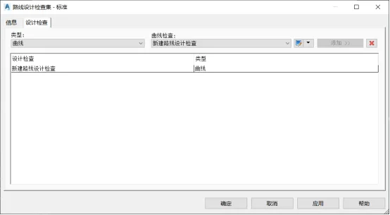
Figure 3: Adding Design Inspection Rules
After setting up the inspection rules, select the route object again and open the route style dialog by right-clicking. Under the Display tab, enable the warning symbol to be visible in the plan view. When you return to the plan view, sections of the route radius that do not meet the custom inspection criteria will be marked with yellow warning symbols, as demonstrated in Figure 4.
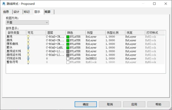
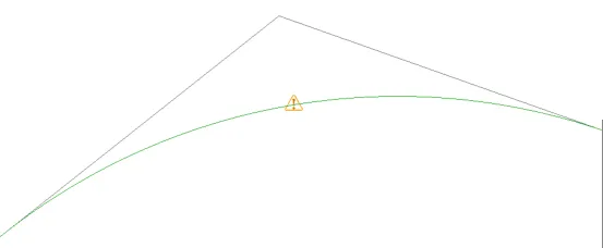
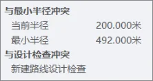
Figure 4: Curve Radius Inspection
Other route-related and longitudinal section checks require customization within the Design Check Editor using Civil 3D’s logical language. The design check dialog offers two categories of object properties: properties and functions. Since different design elements have distinct evaluation criteria, constructing a comprehensive design check expression involves combining mathematical functions, properties, constants, and logical operators based on the selected parameters.
Yang Long (Jilin University of Architecture)
For learning and communication purposes only. Copyright belongs to the original author. If there is any infringement, please contact us for removal.


Must log in before commenting!
Sign Up