The project covers a total land area of 45,473.49 square meters, with a net land area of 33,383.28 square meters. The planned building area is 77,933.84 square meters, while the predicted building area is 78,923.25 square meters. The planned calculated capacity area is 57,419.24 square meters, with the actual predicted capacity area being 58,367.91 square meters. The planned saleable area totals 58,017.82 square meters, and the actual saleable area is 57,017.82 square meters (excluding 1,000 square meters of commercial gifts), with a sales value of 433.93 million yuan. The building is designated for residential use, with a design service life of 50 years. The government mandates a prefabrication rate of no less than 30%, utilizing structural types such as shear wall structures and prefabricated concrete shear wall structures. The seismic fortification intensity is rated at 7 degrees. Although the project’s main volume is relatively small, the assembly rate requirement remains at a minimum of 30%. To optimize costs, the above-ground main structure is primarily cast in place. After completing the main structure to the third floor, construction switches to prefabricated components until the sixth floor, after which it returns to cast-in-place for the capping operation. This project’s main structural engineering demands significant resources, including material storage, large vehicle transportation, heavy lifting machinery, steel bar processing, and various logistical facilities.
Application of BIM Technology in the Design Phase of Prefabricated Buildings
1. Initial Design Phase with BIM. The project’s BIM team first establishes a component model library based on the different specialties of precast (PC) components. Through detailed design of PC components, the upstream process aligns with construction drawings while the downstream process coordinates with the PC component factory. Using Revit software, PC components are assigned physical parameters such as name, category, material, size, and strength. The generated drawings include component layouts, six-view component diagrams, detailed drawings, connection node details, and metal accessory processing drawings. Various components are then assembled as building blocks according to these drawings.
During this process, BIM’s data calculation capabilities are leveraged to determine the size and quantity of various materials for a single project. Component material information and quantity requirements are passed on to manufacturers for production. Special attention is given to underground pipeline design, where collision detection is performed prior to each professional design to avoid later revisions. The list of components is also submitted to the construction team to design the construction schedule and assess required technologies and resources in advance. The project’s main BIM model is illustrated below:
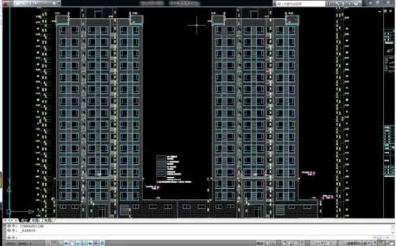
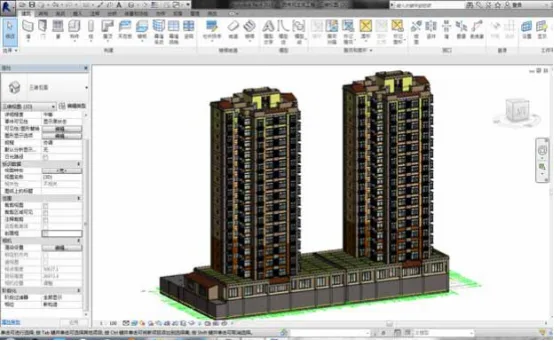
Figure 1: BIM Model Creation
MagiCAD offers mechanical and electrical engineering solutions based on BIM technology. It features a comprehensive library supporting the Revit platform and provides IFC output. MagiCAD allows existing 2D floor plans to be transformed into 3D graphic models without additional drawing or calculations, as shown below:
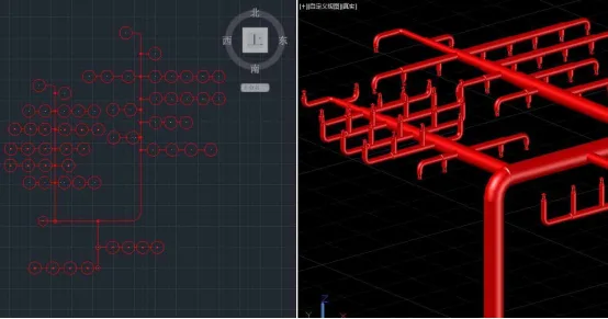
Figure 2: Construction of Water Supply and Drainage Professional Model
2. Design Optimization through Collision Detection. Collision detection and filtering are applied to the constructed model to improve drawing accuracy. Traditional designs rely on 2D drawings, which often lead to design changes on site due to pipeline clashes, affecting schedules. Given the complexity of integrated pipelines and multi-discipline wiring, conflict detection is used before project implementation to optimize roughly 300 collision points, enhancing design accuracy. The collision detection results are shown below:

Figure 3: Collision Detection Results
3. Dynamic Engineering Quantity Inquiry. After revising drawings post-collision detection, quantities of materials such as steel, concrete, PC components, and connectors are calculated using Guanglian Da software. This addresses issues of large errors, unfamiliar rules, and inefficiency inherent to manual calculations. An example is shown below:
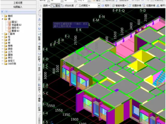
Figure 4: Quantity Calculation
4. Cost Budget Control in the Design Phase. Once engineering quantities are calculated, they are linked to local pricing lists, allowing BIM to compute comprehensive item prices. By associating these costs with construction progress, personnel, and vehicle numbers, the total cost for project operation can be estimated via simple calculations. BIM technology greatly improves budget accuracy and provides valuable data to support project management, as illustrated below:
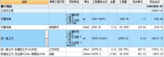
Figure 5: Linking Building Models with Pricing Data
Application of BIM Technology in Prefabricated Component Production
The batch processing and production of prefabricated components are vital for the overall construction process. The accuracy and completeness of component fabrication directly impact subsequent construction progress.
1. Enhancing Component Production Accuracy. The component fabrication factory accesses processing information through the BIM data-sharing platform in real-time. Compared to traditional 2D information, 3D component data provides clearer, more intuitive structural details, reducing production errors caused by misinterpretation and improving on-time delivery for mass production. Embedding RFID technology in components during production allows real-time monitoring of location and status, supporting transportation and installation logistics.
The BIM model offers detailed textual descriptions covering size, quantity, pouring methods, installation positions, and positioning points, guiding the production process effectively.
2. Assisting Construction Companies in Supply Chain Management. Production enterprises upload component processing statuses and procurement contracts to the BIM cloud, enabling real-time monitoring of production plans. This enhances supply chain management, helping companies balance construction schedules with material supply and ensuring smooth, efficient project execution.
Application of BIM Technology in Prefabricated Component Transportation
1. Optimizing Transportation Routes. The component fabrication site is located approximately 20 kilometers from the construction site. Before construction begins, appropriate transportation vehicles are selected based on component size, weight, and tonnage. BIM is used to analyze terrain and topography, helping develop optimal on-site transportation routes that meet environmental and road requirements, reducing transportation costs.
2. Component Transportation Monitoring. Combining BIM with RFID technology allows real-time tracking of components during transit. BIM also supports vehicle transportation simulation to anticipate transportation scenarios, as shown below:
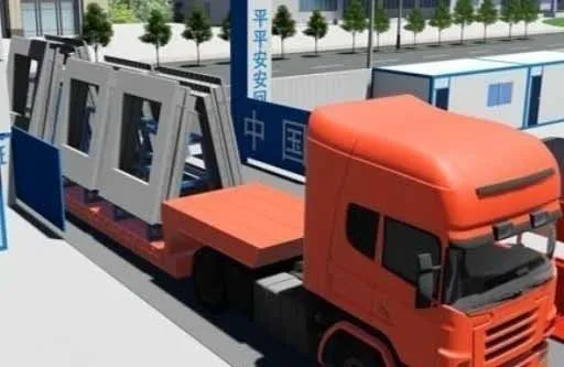
Figure 6: Component Transportation Simulation
Application of BIM Technology in Prefabricated Component Installation
1. Site Layout Planning with BIM. Prefabricated buildings require meticulous advance site layout planning. BIM’s site layout functions are used to organize storage and lifting positions, selecting lifting points based on the largest component size. The site layout during construction is depicted below:
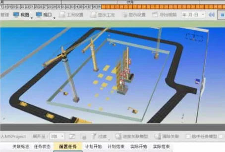
Figure 7: Site Layout During Construction
2. Construction Simulation. BIM software simulates the construction process, enabling visualized construction management and reducing uncertainties. Delivering prefabricated components too early increases inventory costs, while delays cause schedule setbacks and higher labor and machinery expenses. Simulation helps contractors understand project scope and progress, coordinate component deliveries accurately, and minimize costs, as illustrated below:
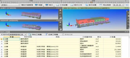
Figure 8: BIM-Based Dynamic Construction Management
Cost Control Results from BIM Application in Prefabricated Buildings
The cost control benefits realized through BIM technology are summarized below:
1. During preliminary design, the exterior wall finish was unified using BIM to change the facade to real stone paint, saving 300,000 yuan and improving quality.
2. Collision detection optimized water supply and drainage pipelines by eliminating 33 unreasonable pipelines totaling 1,580 meters, saving over 50,000 yuan in materials and indirectly reducing costs by more than 300,000 yuan.
3. Exterior wall components were optimized by reducing the number of molds, cutting production costs by 800,000 yuan.
4. During construction, BIM was used to rationally design processes, sequence construction steps, and plan component lifting. This comprehensive optimization accelerated the project schedule compared to similar prefabricated buildings, significantly shortening construction duration and speeding up capital return.
Article by: Cui Ting (Liaoning University of Technology)


Must log in before commenting!
Sign Up