Building B3 of the Longyan Financial Business Center serves as a successful example of applying BIM technology in structural design.
Located in the commercial center, the building features a structural safety level of 2 and a foundation level B. It is designed with standard seismic fortification, rated for seismic intensity level 6 (0.05g), with earthquake grouping classified as group 1, and a basic wind pressure of 0.35kN/m2. The building’s outer frame consists of square or circular steel pipe columns combined with H-shaped steel beams, forming a steel frame (see Figure 1). The core of the structure is a spatial grid, while the exterior surface is formed by circular steel pipes creating a closed curved space, which provides vertical load-bearing and lateral force resistance. Inside this curved space, floors are constructed from H-shaped steel beams intersecting in both directions, topped with pressed steel plates. These two structural systems are connected by a steel bridge. The structural steel used has a strength grade of Q345-B, and the foundation and basement concrete grade is C40.
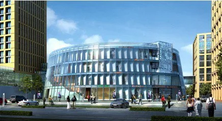
Figure 1: Exterior simulation of Building B3 at Longyan Financial Business Center
A key highlight of this project’s BIM application is using BIM modeling for the structural design (see Figure 2). To ensure model accuracy and improve structural modeling efficiency, the technical team utilized BIM software to create the structural model, which was then imported into structural calculation software. This BIM software not only imports the physical building structure but also integrates structural calculation parameters such as loads, load combinations, and support conditions based on real project data.
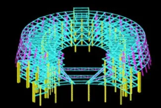
Figure 2: Structural model of Building B3 in Longyan Financial Business Center
Regarding node design between components, the internal grid structure’s vertical members use circular steel pipes, while horizontal components use H-shaped steel beams, resulting in complex beam-to-column connections. Ensuring the overall stability of the spatial grid structure, a rigid connection was chosen for beam-column nodes. Initially, the connection involved two elliptical inserts placed perpendicular at the nodes. However, to maximize node bearing capacity, the combined area of the two circular steel pipes minus the corresponding pipe area on one side of the node needed to be less than the cross-sectional area of the inserted plate. This condition ensures the node’s bearing capacity is theoretically equal to or greater than that of the member.
Using Inventor modeling software, it was discovered that this plug-in plate design resulted in excessive cutting of circular steel pipes in some areas, with the intersection line between the left-side circular pipe and the plug-in plate positioned too far from the right side, weakening the node. After multiple design revisions and simulations, the final solution involved placing an outer plug plate at the upper plane where the two circular steel pipes intersect, and another at the lower intersection plane. These two plates are connected by a horizontal thick plate, as illustrated in Figure 3.
Due to the rigid connection with the horizontal H-shaped steel beam at the node, to effectively transfer bending moments between beams, horizontal outer ring plates were placed above and below the node and connected to the upper flange of the floor steel beam.
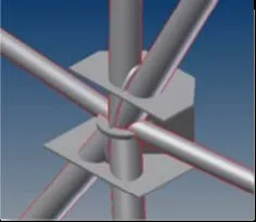
Figure 3: Design of component node connections
Another significant advantage of BIM technology in this project is its use for drawing production. The structural design model was developed using BIM with a split modeling approach, separately modeling the peripheral steel frame and the central spatial grid. Once independently modeled, these components were assembled within the BIM software. This comprehensive structural model then supported structural analysis and revisions to finalize the design.
With the completed model, any plane or section of the structure can be extracted by cutting the model. Moreover, any modifications made to the model or data automatically update the construction drawings in real-time. Given the complexity of the nodes, creating node construction drawings was a complicated and time-consuming task. Therefore, BIM software was employed specifically for producing these detailed node construction drawings.
Throughout the overall structural design process, BIM technology played an essential role, maximizing its benefits by enabling direct import of BIM structural models into calculation software. This approach significantly improved modeling accuracy and simplified the design and calculation of structural components and nodes. Finally, several structural construction drawings were generated from the BIM model, and further detailed design of structural components and nodes was completed in 2D CAD software, resulting in a comprehensive set of 2D structural construction drawings.


Must log in before commenting!
Sign Up