4. 3D Model Reconstruction
The goal of 3D model reconstruction is to eliminate the impact of structural deviations on surface curvature and smoothness. By carefully adjusting the design coordinates, the curvature and smoothness of the ceiling surface model are optimized to meet both design specifications and visual expectations. A critical aspect of handling complex surfaces is to capture key surface features while balancing two considerations: keeping individual surfaces as simple as possible to facilitate model creation, and minimizing the total number of surfaces to avoid an overly fragmented model.
Following these principles, the suspended ceiling surface model was refined to correct coordinate data deviations, resulting in an accurate construction surface model. Details of the reconstructed partial model are shown in Figure 5.
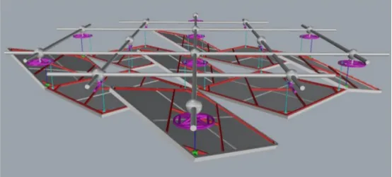
Figure 5: 3D Model of Suspended Ceiling
5. Material List and Processing
After establishing and correcting the surface model, preparing the aluminum plate material list requires accounting for deviations in the XOY plane coordinates of ball nodes, which affect the positioning of ceiling suspension points. Three-dimensional coordinate data for unit model suspension points and unit plate data models are exported to facilitate accurate material ordering.
When cutting curved plates, a 3D model of each unit plate is used for precise calculations. Non-Uniform Rational B-Spline (NURBS) interpolation is applied for constructing each unit plate model. Due to installation deviations of spherical nodes, segmentation lines in planar sections may be uneven and surface segments may lack smoothness. By applying NURBS interpolation, the XOY plane coordinates of each aluminum plate suspension point are fine-tuned. Subsequently, the surface model is redesigned and segmented, ensuring straight segmentation lines on planar sections and smooth curves on curved segments, as illustrated in Figure 6.
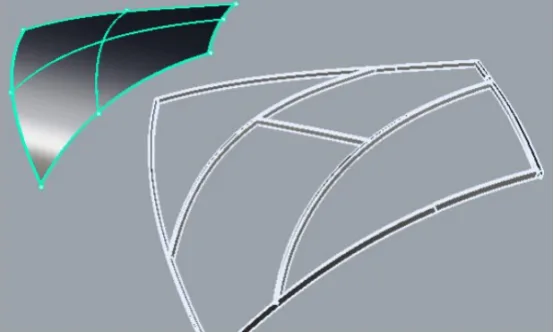
Figure 6: Surface Plate Model
Based on these calculations, the actual processing dimensions for each unit panel—including side length, chamfer, and production parameters—are generated, as shown in Figure 7. The unit block processing material list is provided to the manufacturing factory, where components are produced and later assembled with other parts to ensure construction accuracy.
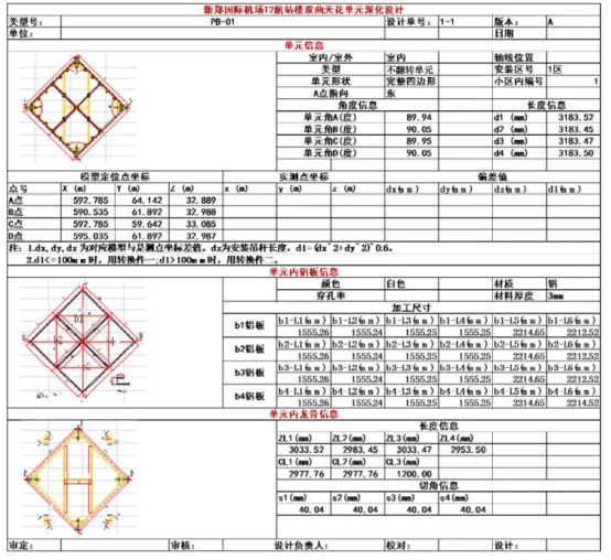
Figure 7: Material Cutting List
6. Panel Installation and Adjustment
During assembly, the factory-produced panels and their components are combined. BIM technology’s visualization capabilities assist in technical briefings on-site, enabling workers to quickly understand each unit panel’s components and specifications. Each unit panel consists of a tray system, clamp system, plate, galvanized square tube, keel, and other elements.
To ensure finished product accuracy during on-site assembly, a mobile aluminum plate assembly platform is first constructed. The platform is measured with a ruler to verify flatness. Galvanized square tubes are welded according to the model’s technical specifications to form rectangular unit cells. The keel and aluminum plates are assembled by placing the keel above the plate, connecting them with specialized connectors, adding anti-corrosion gaskets between metal parts, and securing with bolts. Bolt tightness is inspected and documented to meet quality and safety standards.
Once the unit board assembly passes quality inspection, the panels can be lifted. Lifting plans are selected based on site conditions and the BIM 3D model. Strict safety protocols prohibit anyone from standing directly under suspended units. After lifting, an aluminum ruler is used to verify flatness (within ±3mm) and alignment of plate joints and edges. Any unit not meeting these criteria must not be lifted further.
Following lifting, panel angles are adjusted. Measurements of the four corners of each unit are taken to obtain installation coordinate data, which is then provided to the BIM modeling team for deviation analysis. Errors are corrected by adjusting the suspension rods at each corner. Figure 8 illustrates the adjustment process and its results.
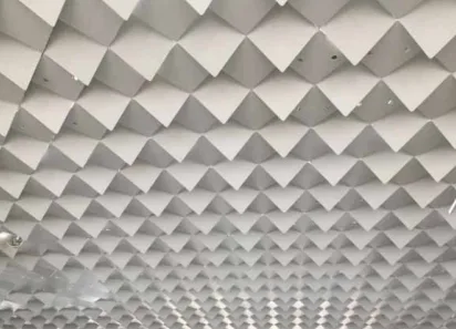
Figure 8: Result of Unit Block Adjustment
Upon completion of ceiling construction, the project manager organizes personnel responsible for design, technology, construction, measurement, and quality supervision to conduct self-inspection and acceptance of all installed work. This process strictly follows technical specifications to ensure the final construction matches the design model. After passing self-inspection, the supervision team coordinates with the owner, design, and construction units to perform the final acceptance.
7. Application of Refined Construction Management Platform
Since the ceiling model is created in Rhino software, importing it into a Revit-based construction management platform requires converting the Rhino model into Revit. Upon import, the model exists as a “volume model.” To facilitate the layout and hoisting of unit panels in suspended ceiling projects, panels are numbered by zone.
In Revit, a “face-based regular model” family is created to label unit panels numerically. Some of these numbered panels are shown in Figure 9.
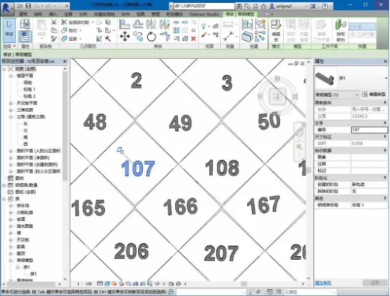
Figure 9: Ceiling Unit Panel Area Numbering
Each project participant can annotate issues through this management platform, recording any problems encountered during construction in the BIM external database. By reviewing problem records relevant to their responsibilities, team members can quickly understand issues and address them promptly. Figure 10 shows an example of problem information recorded within the construction module.
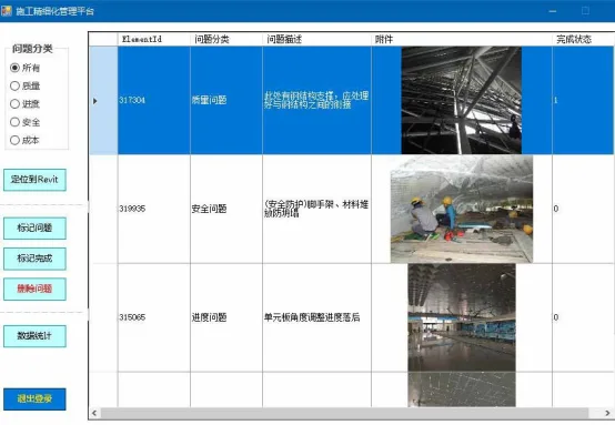
Figure 10: Construction Module Problem Record
8. Engineering Deliverables
Upon completing the ceiling construction project, deliverables include model files, quantity statistics, electronic or paper documentation, and a Revit-based construction management platform database.
Model files encompass ceiling models created and adjusted using Rhino software, Revit-based construction management models, custom Revit family files, models derived from steel structure measurements, other project-related professional models, and process files generated during model construction.
Quantity statistics focus on calculating final engineering quantities. Documentation includes design change records, engineering instructions, and material lists generated during construction. Construction management data delivery involves providing software copies of the management platform and BIM external databases.
Application Effect Analysis
The benefits of BIM technology in ceiling installation projects include:
- Introducing high-precision 3D spatial detection and positioning technology to measure on-site steel structure grid bolt balls, grid dimensions, and node construction errors. BIM software is used to create a measured bolt ball surface model, which is compared against the suspended ceiling design surface to identify and eliminate suspension point errors, resulting in a smooth construction surface.
- Segmenting suspended ceiling aluminum panels using BIM software, exporting material lists for aluminum panels and keels, guiding factory prefabrication and processing, and delivering components to the site for direct assembly. The process utilizes a flexible dual-axis rotating 3D adjustment system and a bottom decoration platform method for steel grid suspended ceilings, enhancing construction speed, safety, and cost efficiency.
- Integrating BIM with lean construction technology to combine their strengths, enabling smooth implementation of project management plans, improving communication and collaboration across project teams, and increasing the efficiency of resolving construction issues.
Note: This article is compiled from online sources and includes content removed due to intrusion.


Must log in before commenting!
Sign Up