The main roof suspended ceiling of the departure hall in Terminal 2 of Zhengzhou Xinzheng International Airport spans approximately 192 meters in width and 522 meters in length, featuring a predominantly white color scheme. The ceiling design incorporates a “rectangle” element rotated along its diagonal axis, creating a unique fish scale pattern formed by the intersection of flat and inclined panels. This architectural texture enhances the uniformity of natural light and meets the functional requirements for indoor aesthetics, lighting, and smoke ventilation. The design effect is illustrated in Figure 1.
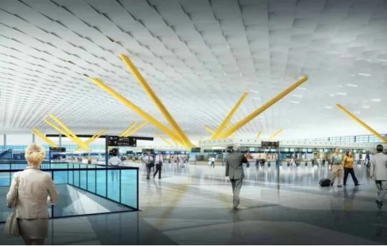
Figure 1: Fish scale shaped double-curved ceiling effect in the departure hall
Project Challenges and Key Issues
While the ceiling installation units are evenly spaced on a flat projection, their dimensions vary when mapped onto the three-dimensional curved surface. The project involves over 40,000 unit blocks, each with unique external dimensions, posing significant design, fabrication, and installation challenges.
During the steel structure truss construction, deformations can cause discrepancies between the actual positions of bolt balls and the design model data, complicating the suspended ceiling installation. Conventional installation methods cannot meet the project’s quality and timeline demands.
The curved aluminum ceiling panels, especially those in concave areas, exhibit complex curvature variations. The 3D model deepening design must account for structural deviations while balancing construction costs and schedules.
The workload is substantial, and precision requirements are extremely high. Ceiling panels must be adjusted to precise angles per the design. The flat and inclined panels are arranged in a cross pattern, with lighting fixtures and other equipment installed on the flat aluminum panels, further increasing the difficulty of achieving high-precision construction.
BIM Application Goals and Implementation
(1) BIM Application Goals
By leveraging BIM technology, this project aims to address the key challenges throughout the suspended ceiling construction process. Applying a refined BIM construction management approach helps improve planning, enhance coordination, and reduce costs and schedule delays.
(2) BIM Application Content
Beyond basic project requirements, BIM is utilized to support precise construction of the suspended ceiling installation, focusing on the following aspects:
① 3D Structural Precision Control
The suspended ceiling is installed directly beneath the main steel framework, which serves as its support. Structural deviations can impact installation accuracy. To mitigate this, comprehensive measurements and inspections are conducted during both the design deepening and construction stages to monitor grid deformations. The ceiling model is refined using BIM software to address and adjust for these deviations.
② 3D Modeling and Material Procurement
BIM software Rhino is used to create 3D models from design data and measured ball node data. The model is segmented into unit blocks for mass production, including extracting unit data and production parameters.
③ Unit Panel Installation and Adjustment
Three-dimensional ceiling nodes are assembled using custom fasteners or universal joints. During panel hoisting and angle adjustment, the coordinates of the panel’s four corners are monitored. BIM technology compares actual coordinates with design values, allowing precise angle adjustments to ensure alignment.
④ Construction Coordination and Management
A Revit-based construction management platform records issues related to quality, progress, safety, and cost during ceiling installation. Stakeholders can access and address problems through dedicated modules, fostering communication and collaboration throughout the project.
BIM Software and Model Accuracy
(1) BIM Software Selection
This project employs Autodesk Revit for civil structure and MEP BIM modeling, Tekla for steel structure modeling, Rhino for ceiling panel design, and Autodesk Navisworks for BIM model integration.
(2) BIM Modeling Accuracy
Rhino software primarily handles the design, including dimensional data for each ceiling panel and fixation node. During construction, Rhino models are imported into Revit, where unit blocks are numbered by region.
The BIM model must include precise information on the position and size of each panel and fixed node, the material properties of components, and unit panel identifiers.
Refined Construction Based on BIM and Lean Principles
(1) Organizational Management
The project involves multiple participants: the construction team, BIM management consultants, designers, contractors, and material suppliers. Figure 2 shows the project organization chart. A lean construction management team based on BIM is established within the organizational structure to ensure leadership and coordination among all parties, facilitating refined project management.
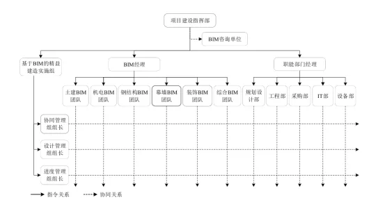
Figure 2: Project Organization Chart
Key management groups include the construction party, BIM consultants, equipment and material suppliers, collaborative management team, design management team, and schedule management team. The coordination management team, consisting of members from the construction party and BIM consultants, enhances collaboration, maintains the BIM platform, and manages documentation. The design management team handles distribution and review of design drawings and 3D models, change management, and model collection. The progress management team oversees construction control, progress tracking, and management of key milestones. This structure strengthens horizontal communication and information exchange among all stakeholders.
(2) Refined Construction Process
The suspended ceiling installation is divided into detailed stages to achieve a refined construction workflow, as depicted in Figure 3.
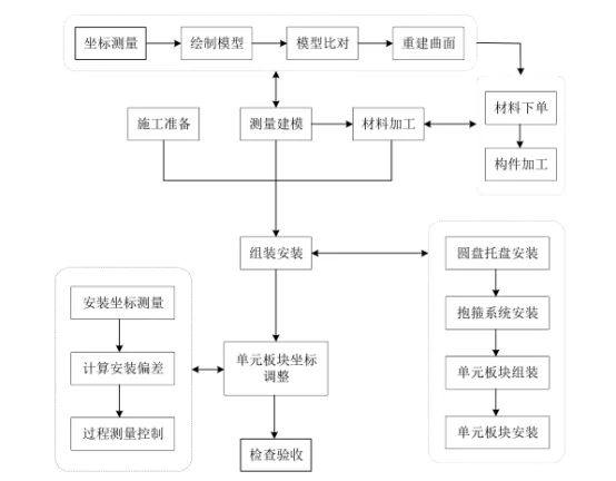
Figure 3: Refined Construction Process for Ceiling Installation
(3) Precision Control of 3D Structures
The goal of precision testing is to gather accurate surface data to support design finalization and construction decisions. Using control points provided by the client, a primary planar control network is established, followed by secondary and tertiary control points. Elevations are controlled via fourth-order leveling. This tight control network is essential for precise measurement and positioning.
Planar control follows a top-down approach, from high- to low-precision measurements. Given the project’s scale and complexity, a multi-level control network is necessary to form an integrated system.
After measuring all feature points, data including point names, design coordinates, and measured coordinates are collected for analysis and modeling. Measurement points for the steel structure are distributed across the entire construction area, as shown in Figure 4.
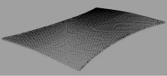
Figure 4: Distribution Model of Measurement Points
To be continued
This article is compiled from online sources and edited accordingly.


Must log in before commenting!
Sign Up