(1) 3D Document Simulation Construction: Utilizing BIM construction models, 3D documents are produced as images and text to simulate complex construction processes or apply specialized construction techniques. These 3D documents serve as direct construction guides on-site, offering high acceptance among workers due to their ease of understanding and portability. Compared to construction animations, 3D documents provide more practical operability, effectively bringing BIM technology into the construction environment.
(2) Visual Construction Briefing: Instead of traditional written disclosures during on-site construction meetings, BIM 3D models are used to visually present construction details and procedures from multiple angles. This approach enables construction personnel to grasp the content from perspectives that are easier to understand. Additionally, BIM models assist in creating 2D drawings that guide the construction of complex nodes, helping workers accurately position steel bars and formwork, thereby reducing rework caused by misinterpretation of drawings.
(3) Prestressed Steel Reinforcement Layout Simulation: Before construction begins, the arrangement of steel bars, corrugated pipes, and prestressed bars is simulated to detect any collisions. After identifying conflict points, the steel bar layout is optimized to meet both design and construction requirements. Using these optimized 3D models to visually guide the construction process significantly improves project quality and shortens the construction timeline.
(4) Reserved Holes Positioning: Box girders contain numerous anchoring points and embedded parts for prestressed steel bars, making accurate positioning of prestressed pipelines challenging. By leveraging 3D models to precisely locate reserved ducts and openings, smooth threading and anchoring of steel strands during subsequent construction phases are ensured. This avoids costly and time-consuming rework caused by reopening holes after concrete pouring, which not only delays the project and wastes resources but also poses safety risks to the finished structure.
(5) Clearance Distance Inspection: Construction environments today are increasingly complex, with many constraints such as limited net height or width. BIM technology is used to verify the clearance distances between 3D model elements. Through real-time walkthroughs, it is possible to check if the net distances meet safety requirements. This continuous optimization of construction plans helps ensure safety and minimizes the impact on surrounding environments.
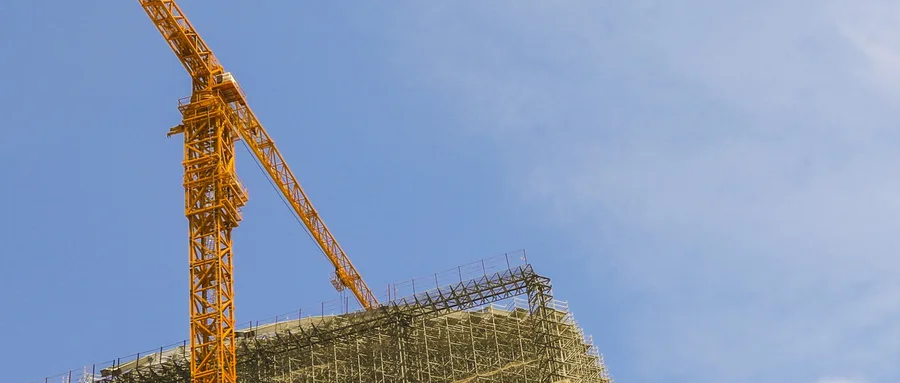
(6) Simulation of Special Templates and Scaffolding Schemes: For complex, irregular structures, the installation of formwork and scaffolding is critical. BIM models are utilized to guide the fabrication of irregular templates and simulate the scaffolding installation process, facilitating precise and efficient construction.


Must log in before commenting!
Sign Up