With advancements in the industry production chain, 3D models can now be submitted directly to prefabricated component factories for manufacturing. Component manufacturers leverage BIM technology to convert design models into processing-ready models, enabling automated component fabrication. This capability is reflected in enhanced component design, optimized production workflows, comprehensive inventory management, and construction simulation.
By utilizing information technology, manufacturers can efficiently manage component data, schedule production plans effectively, and provide timely updates on manufacturing progress. 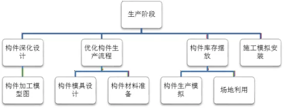
Figure 1: Application of BIM Technology during the Production Stage
During the prefabricated deepening design phase, the number of detailed component drawings is 5 to 10 times greater than in conventional construction projects. These detailed drawings include sectional views from multiple angles, along with precise information about steel reinforcement, embedded parts, and their spatial relationships. The complexity and volume of these drawings make manual modifications difficult and time-consuming, posing significant challenges for designers.
The adoption of BIM technology improves both the quality of drawings and design efficiency. For example, Figure 2 illustrates a detailed 3D model of a concrete composite beam. This model clearly depicts the internal structure, facilitating precise design of prefabricated components.
Based on the completed 3D model, various directional views and cross-sections can be generated automatically. Using Revit’s detailed scheduling features, it is possible to create comprehensive tables summarizing concrete quantities, steel reinforcement details, and embedded part statistics. Finally, the drawings are assembled by dragging views and tables into the layout, then exported in DWG format as shown in Figure 3. In these Revit-exported drawings, each view exists as a separate block composed entirely of line segments.
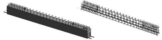
Figure 2: 3D Model of a Composite Beam
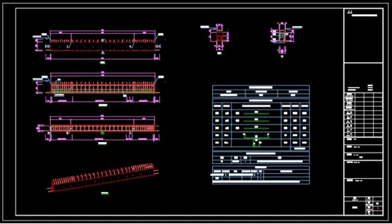
Figure 3: Drawing of Composite Beam
When errors are detected in the CAD drawings, correcting them directly is labor-intensive. Instead, modifications are made within the 3D model using Revit software, after which updated drawings are exported. Correcting errors in the 3D model automatically updates all views, saving time and reducing errors.
To address issues such as computer lag and difficulties navigating large model files, data is stored in stages. This approach allows users to retrieve specific model segments as needed during review.
Currently, most manufacturers in the prefabricated building component production phase use Allplan Precast, software developed by Nemechek Engineering Co., Ltd. This specialized design tool is tailored for prefabricated construction, offering powerful features for high-efficiency, automated design and detailed component modeling. It also enables one-click generation of machining drawings.
By utilizing this software, manufacturers avoid the inefficiencies of creating separate drawings for each component, saving manpower and resources while ensuring drawing accuracy.


Must log in before commenting!
Sign Up