This article is from the official account: Water God talks about C4D.
First, it’s important to understand that wiring isn’t necessarily better when it’s simpler. Overly simplistic wiring can reduce the control over model deformation. The primary goal of wiring is to support textures and animations, and this concept must be clearly understood by everyone.
Wiring Principles
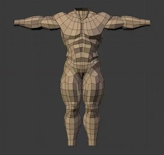
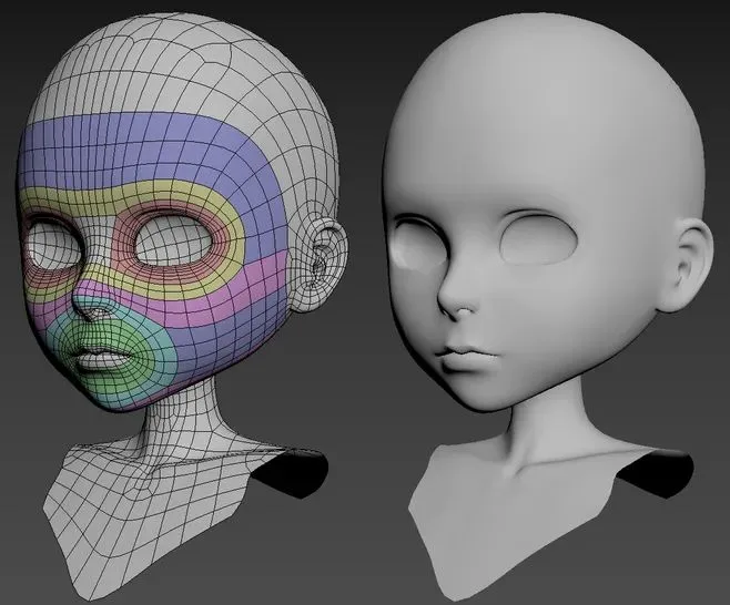
Areas with large motion amplitudes have dense wiring, such as joints, facial expression muscles, and structural parts that experience significant bending. These dense lines are necessary to capture fine details and facilitate smooth animation and deformation.
Conversely, sparse wiring is applied to areas with minimal movement, including the skull, limb joints, and parts with little motion or stretching.
Wiring Guidelines
For regions with significant deformation, wiring should follow an average and logical extension direction to ensure maximum flexibility during motion. In areas with less deformation, wiring mainly needs to accommodate the object’s structural changes, with less emphasis on motion and extension.
The “One-Third” Wiring Method
Many students tend to use the “squeeze” tool to add details. While this command is useful in industrial modeling, it is not recommended for biological or character modeling. Using the “squeeze” command creates five-pointed vertices, which can cause issues during animation.
Instead, the one-third method is preferred. This technique involves restructuring a line into three segments, effectively increasing model detail and ensuring better extensibility for future animations.
Handling Five-Point, Three-Point, Polygonal, and Triangular Faces in Wiring
Polygon modeling must consider smoothing effects. However, five-point, three-point, polygonal, and triangular faces can cause uneven shading and defects after smoothing, so their creation requires careful attention.
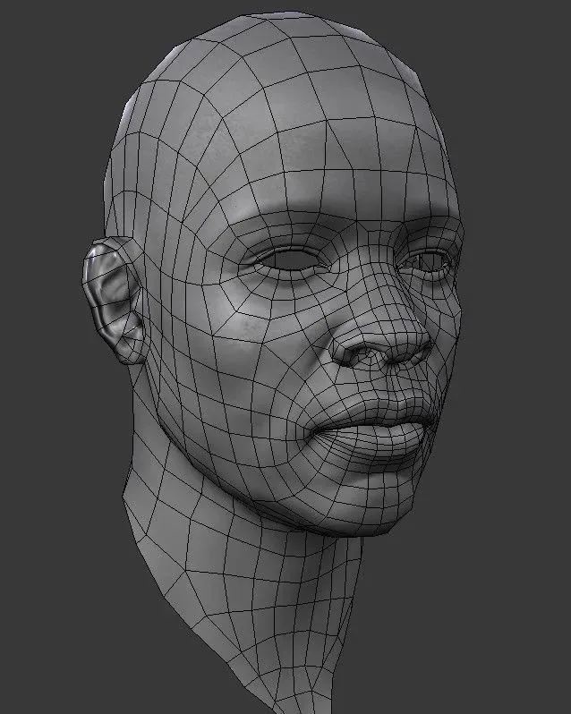
Five-point vertices are problematic for animation control because they mark line direction changes. If a five-point vertex is located where significant stretching occurs, it is prone to breaking during deformation.
Therefore, whenever possible, position five-point and three-point vertices in areas with minimal muscle movement or outside the main line of sight.
After reading this overview, you should have a clearer understanding of the principles and techniques behind wiring in modeling. Next, let’s explore a basic wiring tutorial to deepen your knowledge.


Must log in before commenting!
Sign Up