This article is from the official account: BestBIM.
Accurately placing components is a common challenge in design work, significantly impacting both design precision and efficiency.
So, how can you achieve accurate positioning in ARCHICAD? This guide uses the example of inserting a door exactly 200mm from the inner edge of a wall to demonstrate four precise placement methods.
1. Using the Tracker Tool for Precise Placement
1. Activate the “Door” tool and hover your mouse over the inner edge of the wall you want to reference. Note: Do not click; simply place the cursor there.
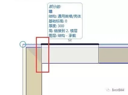
Figure 1-1
2. With the tracker enabled, enter __AI_T_SC_0_>; [200+] and press Enter. This creates a temporary guide line positioned 200mm from the wall’s inner edge. Press Enter again to confirm the door’s placement.
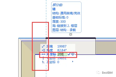
Figure 1-2
3. Choose the door’s opening direction and complete the operation. The final result is shown below.
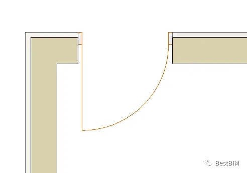
Figure 1-3
2. Using an Auxiliary Line for Positioning
1. Activate the Auxiliary Line tool and draw a line along the inner edge of the wall.
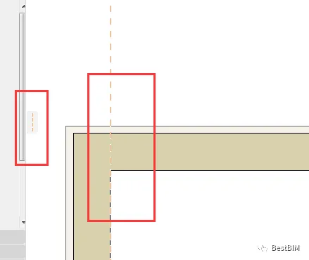
Figure 2-1
2. Drag the auxiliary line inward, offsetting it by 200mm.
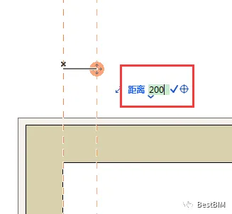
Figure 2-2
3. Activate the Door tool, select the intersection point of the wall and auxiliary line as the placement point, choose the door’s opening direction, and the result will look like the image below.
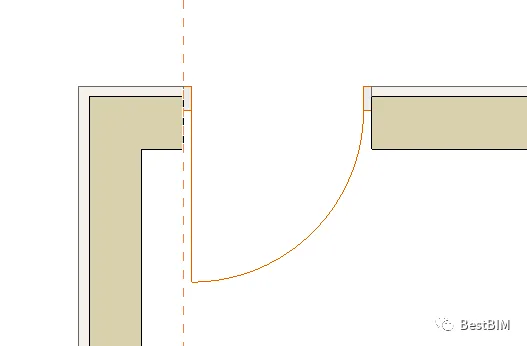
Figure 2-3
3. Using the ‘Capture Assist and Point’ Tool
1. Make sure the “Capture Assist and Point” tool is active and set the capture mode to “Distance (200mm)”.
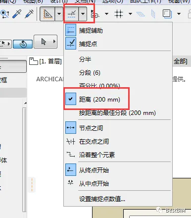
Figure 3-1-1
Note: If the snap distance is not set to 200mm, adjust it by clicking “Set Snap Point Value”.
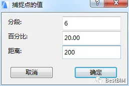
Figure 3-1-2
2. Hover your mouse over the inner edge of the wall. It will be segmented into 200mm intervals as shown below.
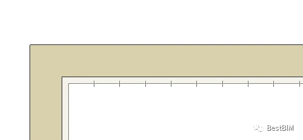
Figure 3-2
3. Activate the Door tool and snap to the first marked position.
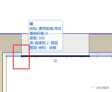
Figure 3-3
4. Click to confirm and select the door’s opening direction. The final placement result is shown below.
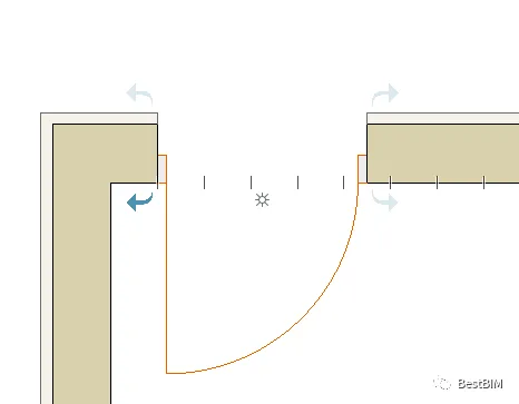
Figure 3-4
4. Using Grid Positioning
1. Navigate to View > Grid & Edit Plane Options > Grid & Background in the menu.
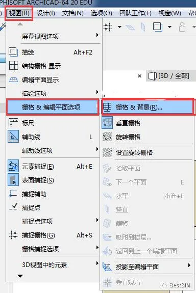
Figure 4-1
2. Set the grid spacing parameters as shown below and click OK.
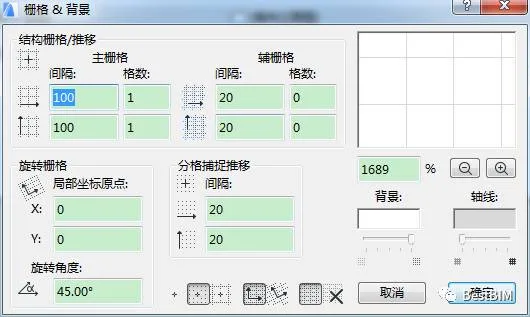
Figure 4-2
3. Click the Capture Grid button on the standard toolbar, then click the black triangle on the right to display the structural grid.
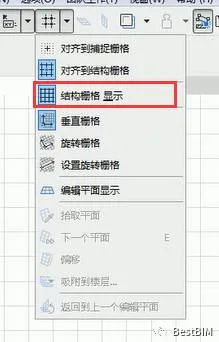
Figure 4-3
4. Since the grid spacing is set to 100mm by 100mm, place the door on the second grid line near the inner edge of the wall.
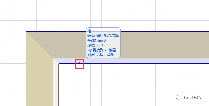
Figure 4-4
5. The final result looks like this.
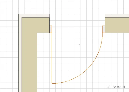
Figure 4-5
These are the four precise positioning methods introduced here. Feel free to use them flexibly depending on your specific needs. We hope this guide helps improve your learning and work efficiency.


Must log in before commenting!
Sign Up